Continue to Site

Eng-Tips is the largest engineering community on the Internet

Intelligent Work Forums for Engineering Professionals

  • Congratulations KootK on being selected by the Eng-Tips community for having the most helpful posts in the forums last week. Way to Go!

o-ring grooves design

Status
Not open for further replies.

Baraa Karam

Mechanical
Mar 7, 2022
21
I'm working on some sort of enclosure, I have some limitation in the overall size of the enclosure, and I'm wondering if there is some guideline for the width "T" of the face next to the o-ring groove (as shown in the attached picture). the enclosure's material is Al.
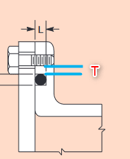
2022-03-07_14h13_27_jucp5z.png
 
Replies continue below

Recommended for you

Seems like a lot of deformation to get a 1.5mm section diameter o-ring to need a 2.2 mm groove width.

If I had to guess about leaking - it's that the tabs that the screws go through will bend before they supply enough force to properly compress the rest of the seal around the perimeter.

 
the tape is 8mm deep into the enclosure, I don't think they will bend.
 
I also doubt that four M3 screws will generate sufficient force to compress the ‘O’ ring and looking at how the bolts are positioned there will be zero pressure exerted on parts of the ‘O’ring, also tapping into aluminium with such a small thread isn’t the best idea.
In short there are bigger concerns regarding it sealing as opposed to worrying about the land thickness on either side of the ‘0’ ring.
In addition if this is submerged in water then aluminium and steels fasteners aren’t the best combination, that said there are still lots of details unknown to us here.

“Do not worry about your problems with mathematics, I assure you mine are far greater.” Albert Einstein
 
I'd still like to know by what process is this going to be made?


Politicians like to panic, they need activity. It is their substitute for achievement.
 
you mean the purpose of the enclosure or how the enclosure will be manufactured?
 
Hi

Seconding guessing Pud but I think he means how the 0 ring groove will be produced within the oval shape.
I guess the oval shape will be extruded but then you need to hold it in someway to machine the groove and holes etc.

“Do not worry about your problems with mathematics, I assure you mine are far greater.” Albert Einstein
 
MinJulep: why do think it is going to leak?

Because:
[ul]
[li]The sealing face will not be as flat as you imagine it.[/li]
[li]The cover will not be as flat as you imagine it.[/li]
[li]The cover is not as stiff as it needs to be.[/li]
[li]Thermal expansion and contraction of your enclosure will cause the sealing face to become even less flat than you imagine it.[/li]
[/ul]
 
How it's made? I meant the part before cover fixing holes. Can't seen how cnc machining will work to machine under the flange. The only processes i can imagine is either gravity sand cast, additive manufacturing or lost wax process.
I hope it's a high value-added product.
Prepared to be educated/astounded!


Politicians like to panic, they need activity. It is their substitute for achievement.
 
Pud said:
How it's made? I meant the part before cover fixing holes. Can't seen how cnc machining will work to machine under the flange.
the enclosure will be completely CNC machined from Al. also it will be anodized after machining.
MintJulep said:
The sealing face will not be as flat as you imagine it.
The cover will not be as flat as you imagine it.
The cover is not as stiff as it needs to be.
Thermal expansion and contraction of your enclosure will cause the sealing face to become even less flat than you imagine it.
since all the part will be CNC machined then I have control over the surface finish and surface roughness. and I think the 3mm enclosure walls would be stiff enough due to its small size.
the only concerns I have are about the "T2" , and the thermal impact on the o-ring & the enclosure.
 
Make the oring gland wide enough so the oring does not completely fill the gland. This will allow expansion space for the thermal effect on the oring and prevent it from pushing on the cover.

Ted
 
Baraa Karam said:
the shape of the enclosure is oval cone,overall size )62 * 56 oval * 100 length), the cap or (lip)is at the bigger end, the shape is hollow with 3mm wall thickness, the lip is simply an oval 3mm thick Al sheet with 4 drilled holes for the screws, there are 4 * M3 screw to fix the lip to the enclosure, the screws holes are placed within the oval shape, the o-ring groove is in the oval cone part as shown in the picture, the T1, T2, and groove width (W), if I use 1.5mm o-ring that requires 2.2mm groove width , then the remaining width of the wall (within the groove depth) will be 0.8mm. So my concern is, if I made T1=T2=0.4mm , will the (T2=0.4mm) withstand the force due to external pressure (20 KPa) or will it fail (break or crack)?

i would rather do a stress analysis for a case like this, unless you fill up the internal with oil, then I don't care too much about the rest dimensions.

R.Efendy
 
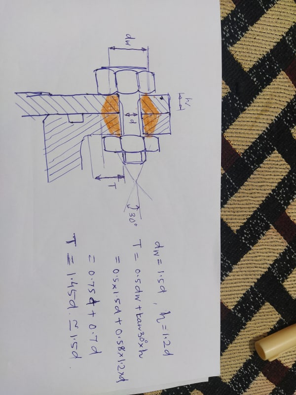
please change the wall thickness and calculate again.
Hope this will help you.
IMG_20220330_055325_lwgqcc.jpg
 
tk10 said:
please change the wall thickness and calculate again.
Hope this will help you

Thank you for your answer.
although your solution seems acceptable, but the actual shape of the enclosure is not like you draw it. but still I'm interested in your answer , could you provide me with the reference of your calculation?

Thanks again.
 
for reference of my calculation see RL Norton machine design book.

For this special problem, in my opinion
0.4mm thickness after o - ring groove of Al wall seems very thin for resist deformation and accidental damages,why not increse it a little as per your past experience or to 1 to 2mm on both side of groove.

Or tugboateng's opinion to use gasket seems good.
 
tk10 said:
for reference of my calculation see RL Norton machine design book.

can you refer to the exact page of the equation you used?
 
Status
Not open for further replies.

Part and Inventory Search

Sponsor