Eng-Tips is the largest engineering community on the Internet

Intelligent Work Forums for Engineering Professionals

Odd size port needing a screw that will fit 1

Status
Not open for further replies.

MechEMines

Mechanical
Jun 5, 2023
6
0
0
US
So I have this odd size port for a transducer that is 0.5906in diameter. I need a way to keep the transducer in this port since it will be measuring considerable pressures: rated to 10k psi. I can get a retaining ring - but I was thinking I could also do something a little more robust like a threaded retaining ring or a bolt with a thru port for the wires to reach the PCB, but I'm struggling finding the right size... do I just need to have a custom bolt created? Any recommendations are very welcome. Thank you in advance for reading.

 
Replies continue below

Recommended for you

What do you mean by "port"?

Plain pipe, socket, threaded ???

Can sketch this? You can see it but we can't unless you tell us.

Remember - More details = better answers
Also: If you get a response it's polite to respond to it.
 
Oh, that's easy - you just buy a plastic caliper with the extra digits in the display. My new one allows me to read to micron precision before the feature has even been machined.

A.
 
Hi all, thank you for your responses!

tygerdawg, yup! But I would need extra material for the threads to have the pitch diameter required for a 15mm screw.

MintJulip, that would be great! Do you have a recommendation? I don't have enough exterior material for a 16MM screw.

BrianE22, yes, it doesn't include retaining recommendations or describe sensitive areas, though luckily the electricals that I work with know the failure points and dos/don'ts.

LittleInch, see link; I edited my post.

dvd, many ways - I prefer a dial gauge micrometer.
 
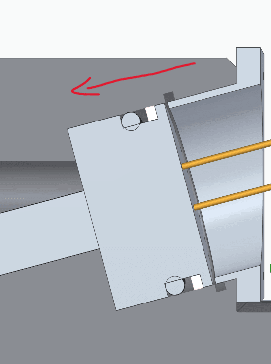
So what I'm seeing is a stepped machined port at an angle to the outer edge with some sort of instrument with a single O ring seal?

I assume that disc shaped circlip type thing is what you have at the moment holding in the instrument at 10,000 psi?

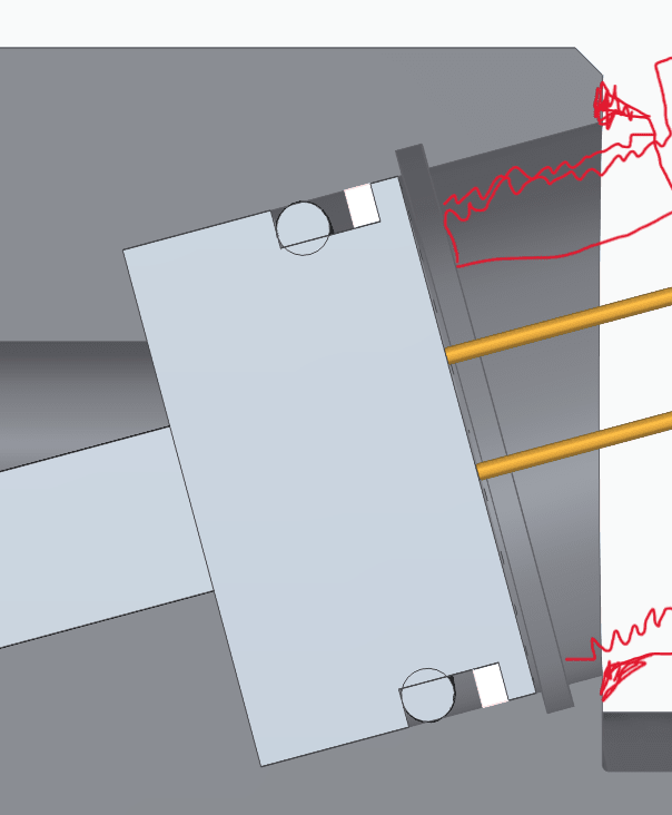
That bottom edge is the weak point as I'm sure you know, but it doesn't give you any metal to add anything really without adding / welding on an angled boss in which to screw in a holding bolt. Like I've drawn in red.

Screenshot_2023-12-08_090806_ld52mt.png


Remember - More details = better answers
Also: If you get a response it's polite to respond to it.
 
LittleInch, yup! The critical areas you described are my concern and that is a retaining ring groove that the screw you drew is touching. If I were to do a threaded component to hold the transducer I would negate the retaining ring groove. I hadn't thought of spot welding as an option so thank you for that idea! I'm unsure we could do that with the sensitivity of the wires but that is something I'll look into. Maybe a retaining ring is the best option for holding this in at 10,000 psi, what do you think? Also, thank you so much for your response!
 
As a simple way I think you check out the force on the item and then check shear strength of your retaining ring.

But 10,ooo psi will give you a lot of force and the thought of this thing failing and shooting out is rather frightening.

I didn't say spot welding, I said fillet weld on an angled screwed insert which could then have a machined out plug to allow the central wires to feed through.

Is this thing built and operating or what?

How was it going to be secured in position?

Remember - More details = better answers
Also: If you get a response it's polite to respond to it.
 
Or instead of a circlip you use a segmented plug with a lower flange (lip).
The are a pain to install a segment at a time and get to fit, and then you put the center plug in and bolt the retainer plate to the top.
I have made these from various materials, the stronger the more difficult to machine.
but because in the end they are virtually solid they don't suffer the ring rolling type of failure mode.
It truly ends up pure shear.

= = = = = = = = = = = = = = = = = = = =
P.E. Metallurgy, consulting work welcomed
 
That bottom corner though is going to be your issue.

Can you not drill it a bit deeper?

Remember - More details = better answers
Also: If you get a response it's polite to respond to it.
 
I'll have to look into the simple way with checking the shear strength of the retaining ring. I tend to over complicate a design at first and then go through several iterations of making simpler and simpler - still learning how to make it simple from the start.

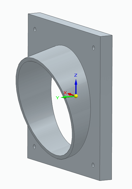
I think the fillet welding an angled screw inset might be an issue for two reasons - heat affected area damaging the transducer and in the screenshot below with the red arrow shows the direction of installation of the transducer, so there's no option to weld the angled screw insert without the transducer present. It also includes a rough sketch of something I thought of just now - second screenshot has better view of that by itself though.

Screenshot_2023-12-08_112028_wolyhr.png


Screenshot_2023-12-08_110954_rirpac.png


I hadn't determined a way I'd like to secure it in place yet - I've been fiddling with the location and had to figure that first since it will be measuring pressure with direct contact to the fluid. I really was thinking a retaining ring.
 
Always wise to investigate when your instinct tells you you could do with something a bit more robust.....

Some gash back-of-envelope calculations suggest that 10,000 psi acting across a 15mm diameter would exert about three times the load you'd normally expect a 15 x 1 mm DIN 472 internal circlip to retain (and scaling off the diagram, I think the groove is too narrow to accommodate even that thickness of clip).

Is there any scope for cutting the 15mm section of the port substantially deeper, leaving more room at the outboard end for effective fastenings?

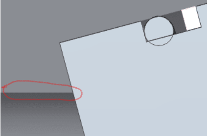
What's the paler grey section at the top of the sketch?

A.
 
EdStainless, is the drawing I just did somewhat picturing a segmented plug with a lower flange (lip)? I could replace the extruded metal plug portion with a rubber insert and create a flat plate with a through hole to allow room for the wires - allowing some give to the transducer and reducing the chance for failure.


LittleInch, I can't drill too much deeper since the wall thickness between the transducer and bore where the fluid will flow through is about 0.125" and with 10,000psi I need all the wall thickness I can get [laughtears]
 
Zeusfaber, the paler grey section at the top is the second screenshot but in the assembly in a section view. I'll have to adjust the dimensions as the vertical height is too large for this application, but I thought it worked for conveying a rough idea. Love the description of back-of-envelope calculations.
 
Your second screenshot is a much better idea IMHO. Think your bolt holes look a bit puny and you might need more.

If you can make the square end round with constant depth then you can easily add more holes - you might even be able to use a standard slip on flange, but whatever - its a much better thing than the inner ring.

Remember - More details = better answers
Also: If you get a response it's polite to respond to it.
 
I keep reading things here that make me think maybe I've got the wrong end of the stick.

What's the transducer intended to measure? The original post implies pressure. If that's the case, then a much smaller hole and an external transducer could be worth a look (the thing that's driving your design problems at the moment is trying to accommodate the transducer body within the vessel wall).

My question about the section at the top of the sketch wasn't worded at all well. I should have done a screen shot, marked it up, and asked:

Screenshot_2023-12-09_095233_tntyyq.png


"What's this feature?"


the wall thickness between the transducer and bore where the fluid will flow through is about 0.125" and with 10,000psi I need all the wall thickness I can get

Where is this 0.125" wall, and is it continuous? Sounds like it separates the transducer from the pressurised medium, somewhere out of shot to the left of the sketch? If so then, if it's continuous and pressure-containing, the transducer itself (presumably not for pressure then) won't be pressurised and retaining it suddenly becomes much easier - and if the wall is pierced and non-pressure-containing, then its thickness needn't be affected by the system pressure.

A.
 
Status
Not open for further replies.
Back
Top