Continue to Site

Eng-Tips is the largest engineering community on the Internet

Intelligent Work Forums for Engineering Professionals

  • Congratulations LittleInch on being selected by the Eng-Tips community for having the most helpful posts in the forums last week. Way to Go!

Offset keyway datum UAME must remain parallel to primary axis datum A confusion

Status
Not open for further replies.

sendithard

Industrial
Aug 26, 2021
186
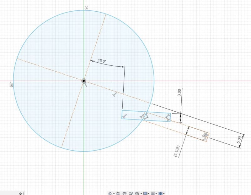
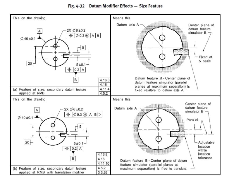
I'm making my way thru the standard to cement it all and the below pic raised my eyebrow.

Since the keyway locks the mutually perpendicular planes in rotation, and it has an offsetting basic dimension, they are saying the keyway UAME(unrelated actual mating envelope) must be set at this distance AS WELL a maintain a parallel relationship to one of the planes.

Does this mean if the keyway was actually made 5 degrees off angle(and this wasn't properly controlled) that when you set up the UAME it must be in reality or in theory placed into the keyway parallel to said plane, which would mean it may only go in 20% of the depth due to the poor angularity?

offcenter_keyway_y5i723.jpg
 
Replies continue below

Recommended for you

Hi, sendithard:

The keyway is located 5 away from datum axis A. The keyway is controlled by a distance rather than an angle. Your "5 degrees off angle" does not make sense here.

Best regards,

Alex
 
jassco,

I had a deep think about this...apologize for any confusion.

Do you use the unrelated actual mating envelope to get the actual size of the feature for measurement purposes, yet to establish the datum feature simulator you would use the related actual mating envelope as it must pass parallel to one axis since it is a secondary datum?

In the top right picture you can see it is machined at a poor angle. So to hard gage this if the feature is at a poor angle the feature is going to have a grossly larger width than a hard gage could be placed into the featue if it was machined at a poor angle.

Make sense?


The gauge expands, just like the mating part would.
 
3DDave,

But does the gauge expand in the related orientation or the orientation you would use to define the keyway width? For datum creation it seems it must be oriented properly to the axis.

If you confine the gauge to be in the orientation of a perpendicular relationship to the axis it cannot be related to the way you independently measure the feature size.
 
Here is a crude example of my mental block. You machine a keyway grossly bad at 15 deg incorrect, and there are no tolerances in place to prevent such a bad keyway.

It is also machined at the largest limit of size being 3mm. So then you go to hard gauge this and you are looking at a minimum of an expanding gauge of 3.1mm in this crude example and you have little if any surface area for the gauge. I'm struggling getting my head around this. I believe you use the unrelated AME to get the width of the feature of size, but then are we using the related AME to lock in the second datum frame?

Capture_gx9zfv.jpg
 
Edit: This was while the diagram post was made, but I think it is still applicable.

In the (a) case it expands centered on the offset.

In the (b) case it floats to maximize the expansion. The standard's explanation is garbage in that the center of the expanded simulator defines the axis and the rest of the fixture is oriented to that. The diagram comment that an axis is parallel to a plane is only into/out of the paper, not to the little dashed lines they draw extension lines to. The diagram should have had the "parallel" axis arrow point to the location of the axis, as part of the "Datum axis A" in "Means this"

In neither case have I seen a realizable assembly use either of these properties.

They are relatively trivial for CMM software, which looks to me like the main reason for including them - it's a GPS feature that is horribly expensive to make a gauge for so it bolsters marketing materials.
 
sendithard,

Yes, there are various types of envelopes in play here.

To establish conformance to the Rule #1 boundary of the slot, an gage block (of width 4.9) would be used. It would not need to be aligned to anything. Alternatively, the Unrelated AME could be measured and it would need to be 4.9 or larger.

To establish conformance of the 0.2 Position tolerance to A, the Unrelated AME of the slot would be used. It would need to be within the 0.2 tolerance zone.

To line up on the slot as datum feature B in Figure 4-32 (a), a Related AME of the slot would be used. It could be called a Location Constrained Actual Mating Envelope.

To line up on the slot as datum feature B in Figure 4-32 (b), a different Related AME of the slot would be used. It could be called an Orientation Constrained Actual Mating Envelope.

The "means this" figure in Y14.5 was unfortunately drawn in such a way that the effect of the translation modifier is obscured. In case (a) the as-produced slot has significant orientation/location error, so the fit with Simulator A is quite skewed. That's fine. But a different as-produced slot was used for case (b), that has little or no orientation/location error. So Simulator B looks like it is still at its basic location, even though it was allowed to translate.

Evan Janeshewski

Axymetrix Quality Engineering Inc.
 
Hi, sendithard:

Datum feature A is primary. Datum feature B is secondary. There is no such thing as "poor angle".

The datum feature simulator for the slot is related to datum A (i.e. it must be parallel to datum axis A).

This datum feature simulator for the slot is expanded while maintaining a BASIC center distance of 5 from datum A at all time.

Best regards,

Alex
 
Hi, sendithard:

I am not sure if I made myself understood.

Your statement below is incorrect.

"In the top right picture you can see it is machined at a poor angle."

Reason that you think the slot is machined at a poor angle is because you are trying to relate the slot to the two holes. Imagine that those two holes do not exist. Then there is no angle. According to the print, the two holes are located to datum A and B, not the other way around.

I hope this makes more sense to you.

Best regards,

Alex
 
Hi All,

I would say that the relationship between the slot and the datum OD can be described in different ways. In the perfect model or drawing, the center plane of the slot has a certain relationship to the datum axis defined by the OD. One way to describe it would be that the projected center plane should "miss" the datum axis by exactly 5 mm. If the part has variation, the projected center plane will miss by a different amount. This variation could be described as location error or as orientation error. I remember having this conversation many years ago in the context of a keyway slot cut into a shaft.

It's kind of like if I'm trying to hit an apple with a bow and arrow. My shot arrow misses 2 feet to the left of the apple. If we look at the arrow's trajectory, it could have reaulted from two different types of error:
1. The angle that I shot at was accurate, but I was standing 2 feet too far to the left (location error)
2. I was standing in the right spot, but I turned slightly to the left so the angle was off (orientation error)

I realize that this analogy is a bit of a stretch. At the end of the day it doesn't matter how we describe the allowable variation, because the requirement is clear. The center plane of the slot must be within a parallel-plane Position zone that has a well-defined relationship to the datum axis.

Evan Janeshewski

Axymetrix Quality Engineering Inc.
 
Thanks for the replies...I think I have an understanding now. The size of the slot should be represented by the maximum gage block placed into the slot with no regards to orientation.

Then due to the fact it is a slave to primary datum A,this feature must encounter a datum simulator that is related to the primary datum axis. Therefore, the measurement of the size of the slot is different than how that slot is used to determine the datum reference frame.

It is taking me a long time to get thru this 2009 section on DRF...what a trying read this chapter is.
 
sendithard said:
It is taking me a long time to get thru this 2009 section on DRF...what a trying read this chapter is.
Once you overcome this section, the rest is much easier.
It is also the basis for most other things.
 
Much easier to understand if there was an example mechanism in an assembly that operated this way, particularly example (b).

Mentioned before - I'm sure before adding this to the standard the committee was show such a design and agreed that this was the only workable approach rather than simply accepting that (b) was the easiest evaluation a CMM software fitting routine could make and not the far more difficult iterative demands of (a). Right? Right?

 
Status
Not open for further replies.

Part and Inventory Search

Sponsor