Eng-Tips is the largest engineering community on the Internet

Intelligent Work Forums for Engineering Professionals

  • Congratulations waross on being selected by the Eng-Tips community for having the most helpful posts in the forums last week. Way to Go!

On-off valve Hookup 4

Status
Not open for further replies.

joji90

Petroleum
Jun 26, 2016
22
NL
Dear members,

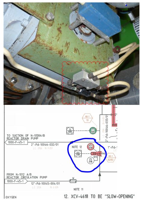
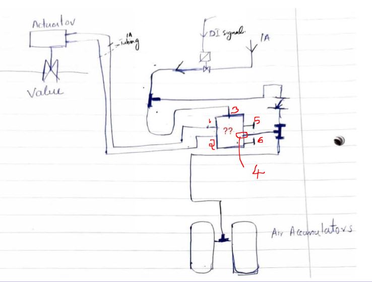
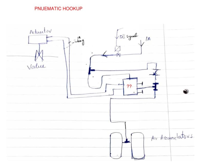
I have a XCV( fail open) and has to be slow opening , the idea is to demolish the old valve and install new one., but when I see the pneumatic hookup of the old valve, I don't understand it, I made a pneumatic drawing from the existing setup but could identify the clouded component and hence couldn't understand the working of the valve. can anyone help please?
Also please check the PDF doc in attatchment for additional info.
XCV10046018_wwiiqo.jpg
 
Replies continue below

Recommended for you

What kind of valve actuator is this? You have it drawn as a rectangle, which makes me think it is a rack-and-pinion actuator. It is unusual to have two air feeds to a rotary actuator that is fail open - normally the double-acting actuators are the ones that require two feeds.

Unless you've missed something in the drawing (like the solenoid valve being a 3-way valve instead of the 2-way valve that you have drawn), that "??" box has to be some kind of bleed valve for when air supply is shut off. There are no other bleeds shown on the system.

Have you cycled the valve and see where the air is discharged?

 
The box marked ?? appears to be the manual open close control box.

In their you will find the small needle valve which controls the opening air flow and speed.

The second line is a little odd, but is either the vent line or they need two pipes to get the flow through the pipes to the actuator.

an actual picture of that box would help a LOT

Remember - More details = better answers
Also: If you get a response it's polite to respond to it.
 
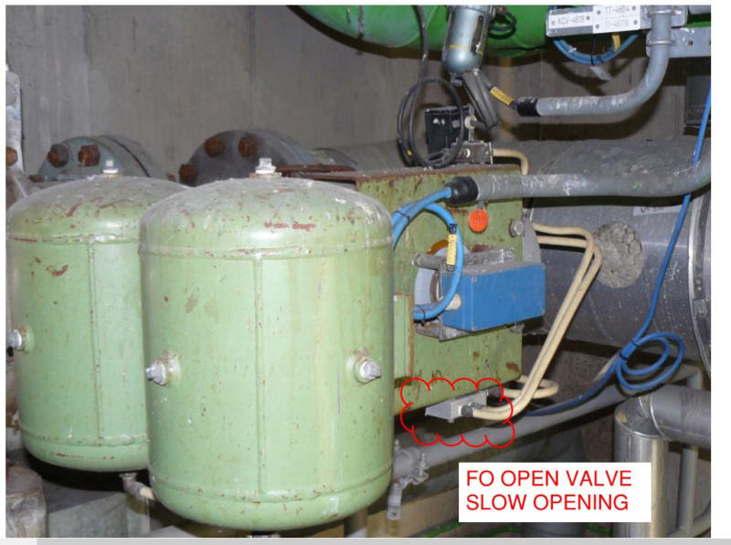
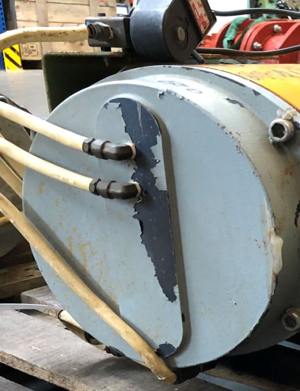
Thanks for the response guys , I'm not sure why my attachment wasn't getting uploaded last time, nevertheless I'm posting pictures of the actual valve below, 2 connections to the actuator is what is surprising me, could be the exhaust being regulated for slow opening? As per the PID , it should have been a single acting( spring return actuator).

XCV10046018_2_kecmag.jpg
XCV10046018_1_qje4rh.jpg
 
the problem is the valve overhaul company delivered new assembly with new actuator( double acting) thinking the old one was double acting seeing the two air connections. I asked him about the component in clouds, but it doesn't have anything written on it. physically the old valve assembly are not with me anymore.
 
Very odd. Your diagram makes no sense though as the DI signal only seems to act on the air inlet line. But those accumulators will keep the valve open surely.

You need to try and find the valve actuators diagrams in the P&ID legend sheet to figure this out.

Remember - More details = better answers
Also: If you get a response it's polite to respond to it.
 
If you have already removed the old valve and are installing a new valve, why does it matter? You know it should be fail open, and the old setup will not be what you are installing now, I presume.

Those two protrusions in your first picture - the ones out the back of the box - look to be needle valves, presumably to control opening and closing rates. I stand by my original thought that this box regulates filling and bleeding of air pressure, but LI is right in his assessment that the arrangement makes no sense as it is piped unless the internals are more complex. As soon as the IA feed line solenoid valve (DI signal) shuts down, the whole system will be suspended at the IA supply pressure. The DI signal turning off the valve doesn't change the state of anything further downstream, so I'm not quite sure how this valve actually operated.
 
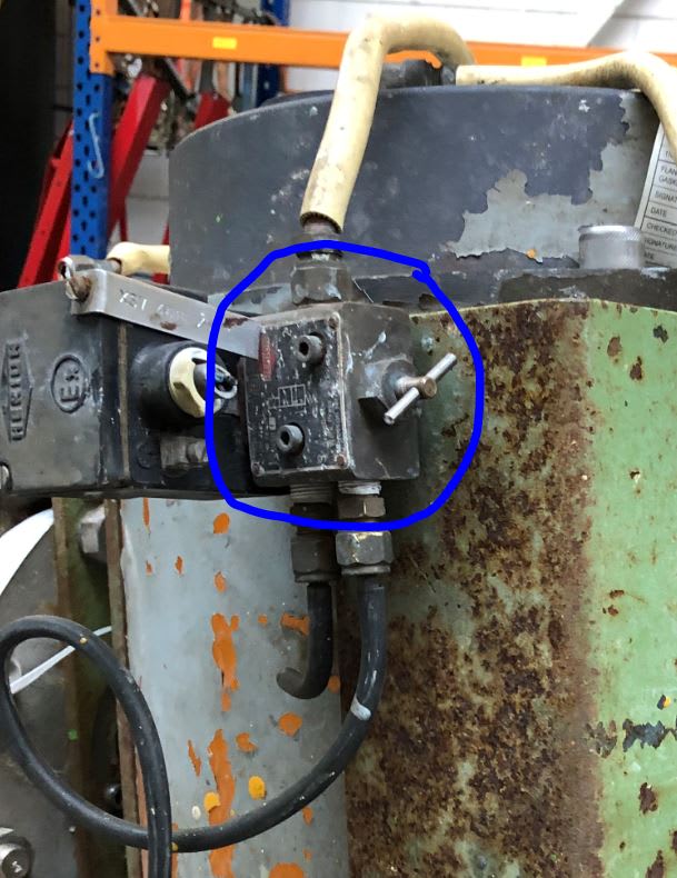
The actuator is a double acting pneumatic type. The valve with the question marks is a 5-way air-piloted spool valve with two cylinder ports to the actuator, one (center) air-supply port, and two (each side of center) exhaust ports. The two exhaust port allow for individual control exhaust flow from each port with flow control valves. The exhaust flow rate controls the actuator speed. This flow is adjusted by needle valves inside the sinterred-brass mufflers on these ports. There should be adjustment screws projecting though the tops off the mufflers.

I think there is an error in your flow diagram. The tee shown down-stream of your solenoid valve should be up-stream, although things may work the same as you have drawn things. The solenoid valve is probably actually a 3-way valve that exhausts air though a small port.
 
Looking closer at the pictures I see that you have drawn the Tee in the correct location on your flow diagram. The check valve isolates the pilot line from pressure in you accumulator tanks.

The 5-way valve has only one pilot port so it must be spring return. And the solenoid valve must be 3-way or it serves no purpose.
 
@TiCl4,Little inch-Thanks for the reply, I'm just wondering how the old valve functioned. That's why I'm trying to find out what that thing in question was actually.

@ composite pro, Thanks for the reply,, the solenoid valve is indeed a 3/2 valve that controls the main air downstream as you see from the picture below.
XCV10046018_4_gvk1k3.jpg
.

Does 2 connections to the actuator necessarlily mean its a double acting type by default? or could one port be for the exhaust of the air?
XCV10046018_3_tnk1hg.jpg


I have numbered the ports , as I understand from the answers above, 5 and 6 are exhausts, while 3 is the pilot line? so in this case this valve is actuated by Air?? can we identify others ports as well?

XCV10046018_5_r1f5dq.jpg
 
My suggestion:

The actual P&ID shows a single acting spring return actuator opening slowly in case of failure, and in reality a simulation with a double acting actuator was installed.

Appears the failure case is no signal on the 3/2 solenoid. In case of failure the instrument air is no longer available and the instrument line to the 5/2 valve is open to the atmosphere due to the 3/2 solenoid. The 5/2 valve switches putting pressure on other side of the actuator, but now from the accumulators. The air on the other side of the accumulator will be free to the atmosphere through the 5/2 valve. In one the outlets of the 5/2 valve there will be an orifice ring to achieve slow opening.
 
I think your DI solenoid valve needs to have the third port shown as a curved arrow venting down.

I assume what happens is that when the DI signal is energised, the 5 port block sees air pressure on port 3 which connects ports 1 & 2 to port 4, which is your air supply.

The valve opens slowly based on possibly some adjustment in that block. I think those two hose are both connected to allow enough air to flow in and out against the spring. The valve then stays held open by the air pressure.

Then to close the DI de energises, the section from port 3 and the non return valve depressurises via the DI vent, the block then switches between port 4 to port 5/6 and the valve starts to close as the air vents to atmosphere and the spring closes the valve.

You don't say anything about how fast the valve closes compared to opening. It may be the closing speed needs two hoses to get the air out of the actuator in 10 seconds? 15? It looks a fairly big actuator.


Remember - More details = better answers
Also: If you get a response it's polite to respond to it.
 
I think, I have to correct myself, and that LittleInch got it right and a single acting spring return actuator was installed. The 2 lines to top of the actuator were most likely there, as they had a different purpose. Could only be verified if you still had the 5/2 valve, or have details of the valve.

Suggestion:
When the 5/2 valve is actuated, instrument air will flow from port 4 to port 1 or 2, or even both. The actuator will close the valve.
When the DI signal falls away, the upper IA system becomes atmospheric. The 5/2 valve switches in position. Now the accumulators air takes over. Most likely port 4 will than be connected to one of the ports 1 or 2, supplying air to the actuator through one of the lines. The other line connected from actuator to the 5/2 valve will be release air through port 5, 6 or even both. Could be that an orifice is mounted in the connector(s). The accumulators make the quantity of air to be released larger giving a slow closing valve operation.
 
The accumulators I have assumed are just there because the valve is a long way from the air supply so during opening the pressure would drop too much.

They normally have nothing to do with valve closure due to spring return action on the piston.

I still struggle getting a grasp of what this system looks like and am using the drawings.


Remember - More details = better answers
Also: If you get a response it's polite to respond to it.
 
I disagree. 5-port valves are used to control double acting cylinders. Ports 1&2 cannot connect together in the valve. One will be connected to air while the other is connected to exhaust, or both will be closed if there is a center position, in the case of a three position valve. This is not a three position valve. It is a two position valve.

The accumulator must be there to move the valve to the desired position in case of air failure, and the valve will stay in that position until air pressure is restored.
 
You could well be right in that one hose is for open and the other for closure.

It's all a bit of a mess without clear knowledge of the box.

Remember - More details = better answers
Also: If you get a response it's polite to respond to it.
 
thanks everyone for the replies.. I'm not going to dig in much as we don't have the valve (??) anymore which is needed to get the actual picture. So I'm going to ask the vendor to make it FO with slow opening, will not use the accumulators anymore.
In the new situation., The flow reducer valve needed in this case to reduce the opening time would be mounted on the solenoid valve exhaust port? does anyone have a drawing with any FO valves with such a setup? maybe there is a special spool valve to do this job?
 
Yes, if you want this to FO slowly then you control air flow on the SV exhaust port. Very common ESD BDV set up. Depending on your SIL level you might have one or two held closed solenoids. The air release valve to control opening speed is usually a needle valve screwed into the exhaust port of the solenoid. they just adjust during commissioning.

It makes no difference to the actuator if the valve is FO or FC - the spring moves the actuator the same - you just need to position the actuator 180 degrees different.

Don't be too hasty about removing the accumulators. They were there for a reason, which is if your air supply drops below min actuator pressure, your FO valve will start to open a little bit as the spring force overcomes the force from the air supply. Unless you n=know for certain that that doesn't ever happen, then the accumulators might be a good idea. Also if your valve is a long way from the air receiver, it might take a long time to close the valve if the air supply pressure drops due to high frictional losses.


Remember - More details = better answers
Also: If you get a response it's polite to respond to it.
 
I agree with LittleInch, be very cautious about abandoning the accumulators. Accumulators are not commonly used because springs are far cheaper, and always have been. They are typically used only where the safe shutdown logic, accounting for all failure modes, cannot be accomplished by springs alone.You need to do a process safety analysis from scratch. But, you have already made changes that require this be done.
 
Joji90 didn't you say that the new valve assembly is with a double working actuator? This would mean there is no spring forcing the valve to go to the failure position. This also would mean you require IA (assuming a pneumatic actuator) to achieve going to the failure position. The required local IA supply system and control system normally depend on the "fault" definition. If not only DI signal fault, but also IA available fault, then you will require a local air buffer to move the actuator to the failure position and keep it there.
 
Status
Not open for further replies.

Part and Inventory Search

Sponsor

Back
Top