Continue to Site

Eng-Tips is the largest engineering community on the Internet

Intelligent Work Forums for Engineering Professionals

  • Congratulations IDS on being selected by the Eng-Tips community for having the most helpful posts in the forums last week. Way to Go!

Operating at extreme left end of Pump Curve

Status
Not open for further replies.

ddkm

Chemical
Nov 9, 2005
94
I have a Centrifugal Pump designed for about 12m3/hr (from purchase information with the supplier). The pump curve is without efficiency lines and as follows:
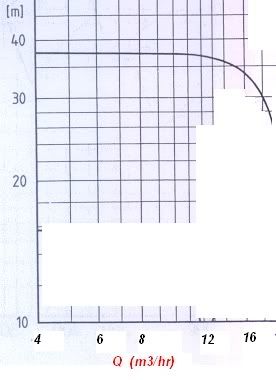
pumpcurve.jpg


We are however, running the pump at only 3.5 m3/hr maximum, which based on the above, means it's not even on the curve. Although I don't have the BEP, but based on the rated 12m3/hr, this means it's about only 30% or less.

This is obviously not ideal and may lead to chronic failures of parts like seals, bearing, etc. The seal has actually failed twice (leak) in the last 2 years. Apart from changing to a new pump altogether, what are the cheaper options to solve this?

a) Install a recirculation line at the pump to increase the flow at the pump? Comments?

b) Reduce the pump speed by installing a variable speed drive?? Comments??

c) What else?

---engineering your life---
 
Replies continue below

Recommended for you

How did you check the flowrate? Do you have a flow meter installed? Alternately, did you check it with respect to power consumption? Presuming that flat curved pump is selected for a specific purpose, for ex. high static head application, I don't suggest VSDs.

The absence of flowrates below 4 cu.mtr/hr, from the performance curve, may indicate that the safe minimum flow is 4 cu.mtr/hr.

The ceapest option would be to change the impeller by a lower diameter one.

A seal leaking twice in two years is not uncommon to me though others may object.

 
quark, there's a flowmeter installed and in fact, the flow is controlled to a maximum of 3.5m3/hr on the pump discharge side.

I've not completed the review of the head required, but yes, it appears that this pump is for a high static head application. Minimum looks like 20m of head, not yet counting the friction losses.

By the way, just from my info alone, would you immediately conclude that running in the range that is absent on the curve (left hand side) is the main cause of the seal failures?

---engineering your life---
 
No, that is a guess work. If your drawing is a copy of the original curve given by the manufacturer, there is no point in omitting the flowrates below 4 cu.mtr/hr unless it is not advised to run the pump below that. Further, 3.5/12 = 29%, which is close to generally recommended minimum safe flowrate.

The seal leakage may be due to 3 reasons.

1. As you are operating the pump at very low flowrate than
BEP, there may be heating up and this may be causing damage.

2. You may have unbalanced seal. A flat curved pump may not cause damage to the seal but there are some chances.

3. Seal type may not be appropriate for your service. If your application is clean water, then strike out this option.

Where is the seal failure exactly? From the primary mating surface or secondary sealing?

 
How is the pump controlled to 3.5 m3/hr?
knowing an inlet and discharge pressure would also help.
what is the application?


Naresuan University
Phitsanulok
Thailand
 

As an example, when the pump is intended to supply liquid to spraying nozzles of a battery of machines, the flow rate will vary with the number of machines. On the other hand, the head would have to be kept constant over the working range of the pump to get best results. In such a case a flat Q-H curve would be the preferred choice.

Answering quark's and Artisi's questions would be a good start.
 
Artisi, as I mentioned earlier, there's a flowmeter and control valve installed on the pump discharge side. The flow is controlled to a maximum of 3.5m3/hr. Application is for oils with normal viscosities, less than 25cP. At the moment, there are no gauges installed on the suction and discharge sides. But we will be installing them soon and will then inspect the pressure conditions.

Quark, your points have also been considered, namely quality (suitability) and installation of seals. However, the very low flow is something that stood out, in my view; thus I was wondering if everyone else here would have just made the same automatic conclusion without further work?


---engineering your life---
 

Ddkm you may be right.

Axial and radial thrusts set up in single volute pumps operating under part loads for protracted periods may require suitable and reinforced bearings.

Worn out bearings are one important possible cause for a short life of the seals.
 
Sustained ops under 40% is absolutely begging for trouble. Its just a matter of when it comes. 60% minimum is suggested by API. If your 3.5 m3/hr is a steady flowrate, you need to change the pump. The use of VSDs is not specially cost effective unless flow varies between 40% minimum and 100%-110% and probaby not even work if static head resistance is more or less constant and remains high at low flowrates.

BigInch[worm]-born in the trenches.
 
BigInch,

If VSD's not suitable, what about installing a Recirculation line at the pump itself which will increase the total flow through the pump? Any comments about how easy to do this?

---engineering your life---
 
The only real disadvantage to that is the product may be subject to heat up due to the continuous recirculation at low flow rates. Recirc at normal flowrates just costs money and usually won't generate much heat. If you must flow very lo for short time periods where heat is a problem, you might be able to provide some additional above ground pipe length to dispose of some of the heat before it gets back to the pump in order to keep operating for a longer time until temp finally gets hi. I have had to recirculate all the way back to the supply tank in one or two situations to mix the heat up with the tank contents. But anyway something like that would probably work fine.

BigInch[worm]-born in the trenches.
 
This particular problem hinges around a pump with a rating of around 3 - 4kW so the economics seem to dictate that fitting a pump that is a better selection for the application is not beyond the realms of possibility.

the flow rate is known, but not the head, which is necessary to make an informed decision on either, how to overcome the problem or to selected a more suitable pump.

To me - pump hydraulics are pump hydraulics as is good design, if this were a 3000kW unit, I doubt you would be happy running it at such a massive turndown in output and expect it the be trouble free.

Calculate or measure the total head of the system (excluding the head loss acros the control valve) and purchase some thing like an inline Grundfos circulator pump rated for 3.5m3/hr at the required total head and sit back and forget about your problems.

Naresuan University
Phitsanulok
Thailand
 
Actually there doesn't seem to be any problems here at all, appears the "thinking" people, although nervous, are supportive of this action. Just one more step in the country's development.

Naresuan University
Phitsanulok
Thailand
 
As usual, there must be some underlying "history" that I am not aware of. I see "somebody" has already called for an end to this and a "return to democracy". Well then, just to wish everything works out peacefully. Take care.

BigInch[worm]-born in the trenches.
 
Artisi, you are right about the pump power. It's rated at 4.4kW. However, I have left out an important point earlier. For most of the time, this pump runs at below 3.5m3/hr, but around once every two days, it is required (preferred) to run 8-10m3/hr for a short period of about 1 hour. (For a different product run).

In that case, I'm leaning closer towards a recirculation line at the pump, which I can then close off whenever I want the pump to run higher flows. Right?

BigInch, I think the heat built-up you mentioned (due to low recirculation rates) should not be an issue. After all, with Recirculation, we are actually trying to increase the flow at the pump, while keeping the net flow at the discharge END to the minimum. Right?

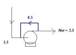
Assuming Recirculation is the preferred solution, then what are the considerations when sizing the new recirc line at the pump? Obviously flow is the main consideration - we may want the recirc line (blue line) to run about 8.5m3/hr, so that the total at the pump becomes 8.5+3.5 = 12m3/hr, as per the original design of the pump.

Recirc.jpg


What do you think?

What other considerations besides flow?


Regards,
DD

---engineering your life---
 
The solution as proposed works, obviously just a bit energy inefficient. Fortunately a rather low power application so, perhaps costing you around $3500/yr. VFD may be feasible, especially if the other product volume requirement becomes a larger percentage of the pump's load someday in the near future. Recirc at 70% BEP appears to be the best compromise available today. It is greatly preferable to running at 30%. Keep the VFD idea in mind.

BigInch[worm]-born in the trenches.
 
Recirculating the discharge straight into suction is something I avoid. The pumped fluid will get heated up continuously. Secondly, even with 12.5 cu.mtr/hr and 40 mtr head, the power consumption should be around 2 kW (pump eff. is 0.7 and motor efficiency is 0.9, considered).

Why not a smaller second pump that is running at BEP?

 
Status
Not open for further replies.

Part and Inventory Search

Sponsor