Continue to Site

Eng-Tips is the largest engineering community on the Internet

Intelligent Work Forums for Engineering Professionals

  • Congratulations IDS on being selected by the Eng-Tips community for having the most helpful posts in the forums last week. Way to Go!

Operating at extreme left end of Pump Curve

Status
Not open for further replies.

ddkm

Chemical
Nov 9, 2005
94
I have a Centrifugal Pump designed for about 12m3/hr (from purchase information with the supplier). The pump curve is without efficiency lines and as follows:
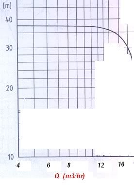
pumpcurve.jpg


We are however, running the pump at only 3.5 m3/hr maximum, which based on the above, means it's not even on the curve. Although I don't have the BEP, but based on the rated 12m3/hr, this means it's about only 30% or less.

This is obviously not ideal and may lead to chronic failures of parts like seals, bearing, etc. The seal has actually failed twice (leak) in the last 2 years. Apart from changing to a new pump altogether, what are the cheaper options to solve this?

a) Install a recirculation line at the pump to increase the flow at the pump? Comments?

b) Reduce the pump speed by installing a variable speed drive?? Comments??

c) What else?

---engineering your life---
 
Replies continue below

Recommended for you

I second Quark. If heat is a problem why not run two pumps in parallel so that one (a smaller pump) can be used for the lower flow <3.5 (m^3/hr)applications and both can be run together for higher flow applications without running at low efficiencies.

Kyle
 
To update this:

I ran the pump yesterday and found that the pressure at the pump discharge (local gauge) showed only about 1.3bar which equates to about 15m Head (based on the fluid density of 900kg/m3). Based on the Total Static Head plus all the Friction Losses in the rather long pipeline, my initial calculation was about 16m for the Total Developed Head. That means both numbers are pretty equal.

To me, this is surprising if we expect the pump to be oversized and currently running on the extreme left end of the Pump Curve. Shouldn't we expect to see a far higher Head in this case? (As per the pump curve in the first post).

Is there something wrong with the analysis?


Regards,
DD

---engineering your life---


Where is the gauge installed? Before or after the valve?

If before the gauge, then, is the pump hunting when you are running it at the part load condition? I read in some past threads that manufacturers deliberately chop off the unstable region of the performance curve. I doubt whether this is the case with a flat curved pump. If you find hunting, then this may also be the reason for seal failure due to the axial movements of the shaft.

 
same question as quark, where is the gauge fitted plus - what duty did you run at -- 3.5 or 8 10 m3/hr

Also the curve it is drawn on log / log paper so the curve, although flat is not really as flat as it looks.

Check with Grundfos pumps - they make a number of 2 and 3 speed pumps - I'm not sure in what size or capacities - but you might find something to fit your duties.

Naresuan University
Phitsanulok
Thailand
 
The gauge is at the pump discharge but before the throttling valve controlling the flow to a max of 3.5m3/hr.

Refer this diagram:

Quark, could you elaborate more on the hunting part? Unless you mean that the curve becomes a Steep Drooping curve at Q below 4m3/hr (which we can't see from the manufacturer's curve above).


Regards,
DD

---engineering your life---
 
What has the pump manufacturer had to say about running at 3.5m3/hr ??? - I'm sure they would caution against it as the pump is probably very unstable at this point.

Naresuan University
Phitsanulok
Thailand
 
We managed to contact the pump manufacturer today (it's a darn old pump...), and based on their reply, the minimum allowable flow is actually 7m3/hr for the heads of 30-40m (as per design).

OK, that much is clear, i.e. we shouldn't be running at the low flowrates.

What I still don't understand is this:
1) If we are truly operating at the extreme left end of the pump curve, how come I don't see the high head of 30-40m on the pressure gauge at the discharge line???

2) Why is the pump designed for 30-40m of Head in the first place, when currently my estimate shows we only require a Total Developed Head of 16m?

Can anyone offer some clues of where I'm going wrong with this analysis????


Regards,
DD

---engineering your life---


Is the impeller still full diameter?

Naresuan University
Phitsanulok
Thailand
 
what is the condition of the impeller, does it have impeller and / or casing wear rings - is it open or closed impeller.

As you can see, there is a number of things were don't know or understand and as we don't have a crystal-ball it's like trying to answer the old story - how long is a piece of string?

Naresuan University
Phitsanulok
Thailand
 
There is definitely a problem with your gauge reading, may be a faulty gauge. The gauge reading should be about 2.3 bar even when the pump is not running, due to the suction static head. So, in running condition, this should be minimum 2.3 bar and should be higher if the pump is running OK.

We would like to get some more data.

1. Is the direction of rotation of pump OK?
2. As Artisi suggested, what is the condition of the impeller?
3. What is the power consumption at the two flowrates?
4. Is your pressure gauge calibrated?
5. Are you hearing increasing and decreasing(rythmic) sound from the pump?


ddkm, something is definitely wrong here. With the pressures and volumes stated, there is nowhere it fits on the pump curve. This may be due to several reasons. Is it the correct curve ? Any reduction on the impeller size ? Any reduction on the number of impellers ? Are the gauges reading correctly ? You may have no option but to physically take dimensional measurements, if the curve is correct. What I also miss here is the speed at which the pump curve stated is measured. If the pump is operated at a lower speed, you expect a curve taking off at a lower pressure of course! (It may have the same profile, but lower pressure range).

You need to check all these.

Again since you said there is a control valve on the discharge, what is the pressure after it ? Also where is the flowmeter located, after the control valve ?

Depending on your answers, a recirculation line may be right, especially since you still need up to 8m3/hr occasionally, but istead of sending it to the suction, it should be sent to a buffer vessel or tank upstream of the pump. This may reduce heating up as it mixes with fresh fluid.

Regards,
Tundelash
 
Some comments as a newcomer to the thread.

1) Pump curve: if the pump is that old, that may no longer be its true curve (maintenance records ok ??). Similar to very old P&IDs seldom representing current configurations (unless a very good doc. tracking/updating is in place which is rare).

2)VSD use
2.1) Why was a pump with that characteristic curve chosen in the first place ?? (is this a "we use it because it was there" situation ?).
If the same design conditions are still valid and a high static head requirement is needed (similar to boiler feed water or oil reservoir water injection applications for instance) with little dynamic flow rate variation requirements (e.g. it runs at a limited number of different flow rates and each runs over relatively long periods of time) then the VSD makes little sense.
A number of pumps in parallel with a suitable Load Management policy (e.g. number of pumps -on- at any given time as per system requirements) would be a more appropriate alternative.
VSDs are usually justified in cases where their particular characteristics as final control elements and/or as energy savings tools are significant. This case appears to be neither.
2.2) VSD vs. PUMP and PUMP MOTOR
When considering a VSD there are issues to be considered with the PUMP. While it is true that Minimum Flow requirement (LOB line) goes down at reduced speeds, there are other issues that may come up at low speeds (e.g. pump shaft defflection, seals temp. and effectiveness etc).
The pump MOTOR also has to be considered for VSD compatibility. If the unit is old, chances are the motor is also old and may need to be retrofitted (re-wound) for VSD use rating (e.g. insulation rating).

If the unit won't be replaced for a more adequate configuration (units in parallel etc.), then Recirculation seems the most appropriate alternative and most comments made so far sound like good recommendations.

Hope this helps (pray tell what you end up doing and how it works).

Regards,
MS


MS
 
Status
Not open for further replies.

Part and Inventory Search

Sponsor