Continue to Site

Eng-Tips is the largest engineering community on the Internet

Intelligent Work Forums for Engineering Professionals

  • Congratulations cowski on being selected by the Eng-Tips community for having the most helpful posts in the forums last week. Way to Go!

Options when there is no room for a header above transom windows on a gable wall. 4

Status
Not open for further replies.

E720

Structural
Feb 20, 2018
71
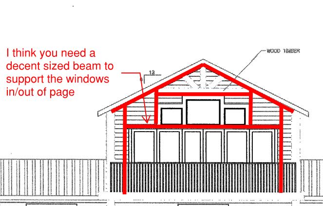
I have attached an elevation of a job I am working on. There is a covered deck on the back and the rear wall has a large opening for sliding glass doors with a few transom windows above it. The roof is all stick framed so there is a point load above those openings from the ridge beam. A header placed directly above the transom windows wouldn't have room to span all the way across the opening for the doors. Usually in this situation I would put a header above the transom windows that post down onto another header placed between the transom windows and the doors, but there just isn't enough room. I feel like here are my options:

[ol 1]
[li]Use what I would call a steel bent or a "cranked beam" where I have steel beams at the slope of the roof and meeting in the middle, designed to carry a moment in the middle, coming down onto steel columns.[/li]
[li] Run the ridge all the way from the timber truss through the wall in question all the way to the other side of the house. I ran the numbers and it would have to be an HSS 14x4x3/8. [/li]
[li] Any other options? [/li]
[/ol]

Thanks,

E720
 
 https://files.engineering.com/getfile.aspx?folder=124f809a-41dc-4ff5-8557-1c7407a6d06b&file=scan0129.pdf
Replies continue below

Recommended for you

And then, there is wind load on that mostly glass gable. How do you handle that?
 
If you run a diagonal from each end of the header above the transom windows to the columns beside the doors, the header over the doors becomes a tension strut instead of a bending member, with the compression carried by the header above the transom windows. It doesn't take much room to put a steel plate in as a tension strut.
 
The 'thinking outside the box' solutions that I see are:

A) Convince the owner to raise the wall heights slightly so that you can raise the upper three windows about a foot or so above the patio doors. This will allow you to put a beam in that can span the entire width. Depending on geometry, you should be able to post the ridge beam down to a lintel above the upper three windows, then down again to the beam between the upper windows and patio doors. This beam will have to take gravity and lateral loads. Likely increase overall thickness of your wall to 2x8 or 2x10 to give your beam a chance.

B) Roughly scaling it, it looks like if you increased the wall height around the entire perimeter by a few feet, you might have enough width to span a beam all the way across above the upper three windows, at least wide enough to post down either side of the patio doors. Some architectural rejigging required.

Not sure I follow your option 2.

Neither are ideal solutions, and have some downside, but if that's what the client wants .... I have assumed that the interior is a cathedral ceiling, otherwise things change.
 
Propose a 4x4x1/2 angle iron (or 6x4x1/2) across the door, with one leg pointed down, so it is across the top of the door frame. If it is a sliging door, there will not be an interference with opening the door.
 
Biggest concern would be for the vertical members framing the sides of the windows... you may want to avoid steel because of cold transfer and condensation within the wall... brown rot issues.

Dik
 
Thanks for the responses. The owner and architect seem pretty set on what they want to do but I might be able to convince them to raise the walls a bit. If not I might explore racookpe1978's option or hotrod's option. Thanks so much.
 
Hotrod's suggestion is a clever way of dealing with the gravity loads, but you still need to resolve wind loads perpendicular to the wall. When the wind hits this wall square on, what is supporting the top of the doors and bottom of windows? I was once called out to a cottage with similar window/door arrangement - if you closed the door with any kind of force the entire wall shook.

I think you need room between the doors and windows to slip in a structural member.

framing_dxuxgq.jpg
 
The lateral load would have to be accounted for, but I assumed there would be, or could be, adequate thickness to the wall to provide lateral bending strength, especially if a steel plate or a rectangular HSS was laid flat.
 
For the scheme I proposed, the gravity loads above the doors would would likely need to be carried by the header above the transom windows, requiring a positive connection of vertical struts beside and between the windows from the header to the plate or HSS over the doors.
 
I just talked to the architect and he gave me a few more inches so I can slip a steel tube in there between the transom windows and the doors.

Honestly the out of plane forces on this wall would be something that the firm I work for never really worries about. We probably engineered that cottage you are talking about CANPRO. I am a young engineer and that's one of the reasons I like reading everything I can on this forum. I really like where I work but I know there are probably gaps in my engineering knowledge and I try to learn as much as I can from my bosses, coworkers, self-study, and this forum.

Having said that, we will now have it framed similar to the sketch by CANPRO. Do I just need to make sure that the steel tube can handle the bending from the wind load about it's weak axis, and make sure the connections to the columns/posts can handle the load in that direction?

Thanks
 
If framed similar to my sketch, the header above the doors will take wind and gravity - but I like Hotrods concept of using the header as a tension tie. If designed/detailed that way, I suspect most of the gravity load will be taken out by this truss action and your header won't take much direct bending.

I think you're on the right track - follow the load path and design the beams/connections accordingly.

E720 said:
Honestly the out of plane forces on this wall would be something that the firm I work for never really worries about

That is a bit concerning. In my experience, walls such as this are largely driven by the wind loading and not so much with the gravity loading. Unless there is a ridge beam framing in at the peak, the gravity loads are likely peanuts compared to the wind.
 
Thanks CANPRO, and, yes, there is a ridge framing in at the peak.
 
Depending on your location the wind loads may govern, particularly if you now view the beam above the door as primarily a tension strut. In that case you might want to orient the beam flat so that the strong axis is resisting the wind load. I also agree that wood might be better than steel if there are thermal conduction issues.

And yes, you need to calculate the wind pressure per ASCE7 or a similar standard and check that the header can satisfy load and deflection criteria.

At the end of the day it has to work. If not, you have to find the strength to tell the architect you can't make bricks without straw.

Edit: I just saw that the roof is stick framed so you will probably need the strong axis of the header for gravity loads.
 
Thanks for the post charliealphabravo. Because there is a significant pt load coming down from the ridge the steel tube in between the transom windows and doors had to be pretty beefy, but I do have it oriented so it bends about its strong axis from gravity, weak axis from wind. I will check the wind pressures. Thanks.
 
dik - I think that is one big opening below for stacking/sliding doors.
 
Status
Not open for further replies.

Part and Inventory Search

Sponsor