Eng-Tips is the largest engineering community on the Internet

Intelligent Work Forums for Engineering Professionals

Orientation of Bursting Reinforcement (Eqn 7.2.4(3) AS3600) 1

Status
Not open for further replies.

Rstructural

Structural
Jul 20, 2023
7
0
0
AU
Hi All,

A question about the calculations for bursting reinforcement in AS3600/AS5100 (I'll refer to AS3600 as the clause is the same).

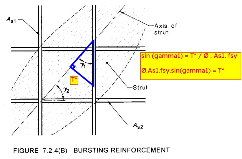
My understanding of the intent of Equation 7.2.4(3) is that there is a bursting force acting at some inclined angle, and in the case of providing orthogonal reinforcement, we are to provide vertical reinforcement to resist the vertical component of the bursting force and similar for the horizontal component.

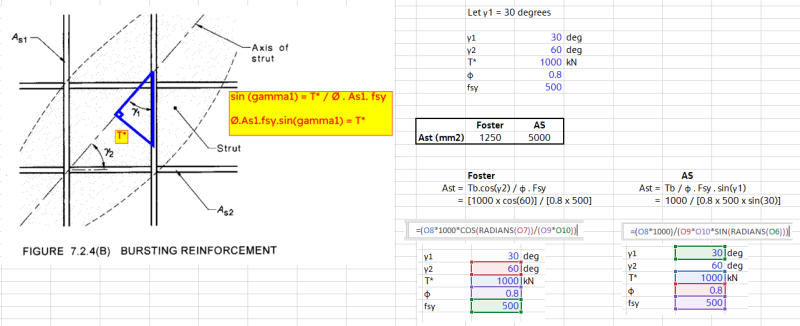
I've attached some notes which may be easier to read than equations in text form below.

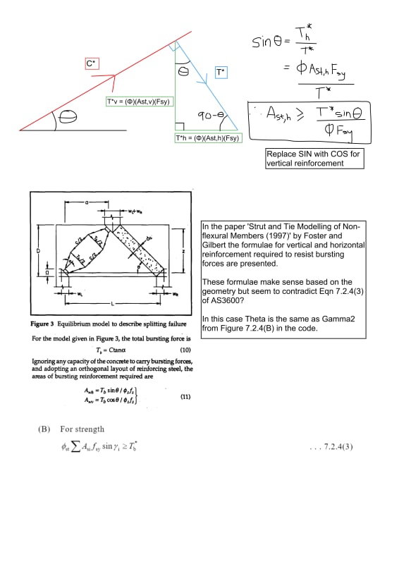
The bursting force acts perpendicular to the axis of the strut. Using the horizontal reinforcement case as an example, if the strut axis relative to the horiztonal plane is at some angle Theta then Sin(Theta) = [(Φ)(Ast,h)(Fsy)] / T* where (Φ)(Ast,h)(Fsy) is the force in the reinforcement to match the horizontal component of the bursting force.

Re-arranging the equation to find Ast gives Ast = [T* x Sin(Theta)]/[ΦFsy].

This is in agreement with Foster and Gilberts paper 'Strut and Tie Modelling of Non-flexural Members (1997)' as well as the Reinforced Concrete Basics textbook by Foster and co.

However, if you were to re-arrange the code Equation 7.2.4(3) you get Ast = T* / [(Φ)(Ast,h)(Fsy)(sin(Theta))] whereby sin(Theta) ends up on the denominator of the equation and based on Figure 7.2.4(B) the same angles are being used i.e Theta in this case is Gamma2 from the figure to correspond to As2, the horizontal reinforcement.

I feel I may be missing something obvious, but the equations from the Foster/Gilbert paper make sense to me and it would seem the left hand side of the code Equation should be divided by sin(Gamma) rather than multiplied? Would greatly appreciate if anyone could point out where I've gone astray.

AS3600_Bursting_Reo_Query_vcfhyp.jpg


Cheers.
 
Replies continue below

Recommended for you

Just a convention thing, the Foster equations seem right to me also. The principle is easy enough to understand - the sum of the component in the direction of bursting for reinforcement in each direction needs to exceed the bursting demand.

The 7.2.4(B) diagram seems to just be constructing a different triangle as it is not measuring the strut angle from the horizontal, rather gamma 1/2 are angles from the reinforcement itself to the strut. This would be more generalised I think to any directions of reinforcement you choose, not just the vertical/horizontal.

pic_njiwcw.png


----------------------------------------------------------------------

Why yes, I do in fact have no idea what I'm talking about
 
Thanks for the reply Just Some Nerd.

I thought it may be a convention thing with a different triangle used, but if you were to run the cases side by side you will get vastly different results.

I believe if you have a vector, in this case T*, and you want the vertical and horizontal components then you need to specifically use the right angle triangle that has the vector in question (T*) as the hypotenuse?

Below I've run a side by side example of the Foster equation vs the code/your sketch for the vertical case. The results differ significantly.


Foster_v_AS_Comparison_dimcyi.png
 
What i think is going on is that by back-calculating the amount of reo required with the AS method, you're assuming that the entirety of the bursting forces are being carried by the vertical reinforcement and are getting the higher result. There's no demand being taken up by horizontal reinforcement. Assigning all the load to one direction also means there's some unresolved component of the force in the bar you have to deal with.
The Foster method splits T* into the horizontal and vertical components first then calculating reo required. There's still some load to be carried by the horizontal reinforcement too.


----------------------------------------------------------------------

Why yes, I do in fact have no idea what I'm talking about
 
That makes sense to me. If you're relying on reinforcement in one direction only then you need a much higher quantity so that the inclined portion can take the entire bursting force. Hence Eqn 7.2.4(3) is specifically for the single direction reinforcement scenario. If sin(gamma) = 90 (reo layer perpendicular to the strut) then it will be parallel to T* and the whole area contributes to resisting the force.

I feel the notation of the clause could be a little clearer, the definition of Asi is "area of reinforcement in directions 1 AND 2 crossing a strut..." so I still read that as it being the formula you use when you have reinforcement in two directions.

But as we've established, by thinking through what the reinforcement is actually intended to do (resist T*) it all makes sense as to what reinforcement is required for each scenario.

Appreciate the discussion mate, always helpful bouncing stuff around.

 
Hence Eqn 7.2.4(3) is specifically for the single direction reinforcement scenario
I feel the notation of the clause could be a little clearer, the definition of Asi is "area of reinforcement in directions 1 AND 2 crossing a strut..." so I still read that as it being the formula you use when you have reinforcement in two directions.

I think it's more correct to frame equation 7.2.4(3) as checking the capacity after reinforcement has been determined and not for use to actually portion out your reinforcement - it's only for i = 1 that the problem arises from having to rely on a single direction. I'd even say that the definition of Asi is slightly too narrow in that the equation can apply to more than just two directions crossing the strut as a matter of technicality, though in practice there's no actual reason to add a third direction when you have two orthogonal ones.

----------------------------------------------------------------------

Why yes, I do in fact have no idea what I'm talking about
 
I think it's more correct to frame equation 7.2.4(3) as checking the capacity after reinforcement has been determined

Yes, I think it's fair to frame it that way. This morning I tried taking the quantity of reinforcement in each direction calculated per the Foster equations and then plugged it all back into equation 7.2.4(3). As expected, the total capacity provided was equal to T*.

So Foster's equations essentially find you the balance point of the reinforcement - it is the amount of reinforcement to provide in each direction to exactly match the component of T* in that direction.

Whereas, the code is allowing you to rely more heavily on one direction than the other if required (which would be more helpful in practice), so long as the sum of the components still equals or exceeds T*.

I wonder then about the 40degree limit set for when you use a single direction. Would that also imply that if you are using 2 directions of reinforcement, if one of them is at an angle <40degrees to the strut axis that you cannot rely on that reinforcement more heavily than the reinforcement in the 2nd direction? I don't believe that is the case, as the 40deg limit is specifically mentioned in the sentence about single direction reinforcement, but just something that crossed my mind.
 
Status
Not open for further replies.
Back
Top