Eng-Tips is the largest engineering community on the Internet

Intelligent Work Forums for Engineering Professionals

Orifice Plate Bending - Mystery Calculation 3

Status
Not open for further replies.

Plungeman

Mechanical
Apr 6, 2022
7
0
0
GB
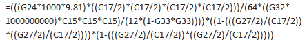
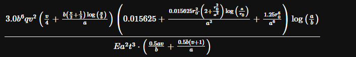
Having joined a new company, I've been tasked to "standardise" a batch of old spreadsheets that are frequently reused. Absolutely nothing give references for the calculations embedded and I'm working to change that. I've managed to track down most of them, but have run into a wall relating to deflection of an orifice plate with a horrendous bit of excel that simplifies to this:

Screenshot_2024-01-16_081427_xo9gkg.png


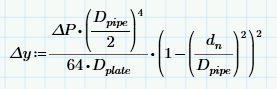
[delta]y = Axial deflection of plate inner edge
[delta]P = Differential pressure
Dpipe = Pipe ID, used as the fixed edge of the plate
Dplate = Plate constant/flexural rigidity
dn = Orifice ID

The values for this are essentially the same as using Roark's 7th Ed Table 11.2 Case 2e (for the range where it's practical to real-world circumstances), but I can't find where this much more compact equation comes from - any pointers?

Edit: Define [delta]y
 
Replies continue below

Recommended for you

And so that someone else can feel my pain, here's the original excel formula:

Screenshot_2024-01-16_082453_pr6fwx.png


G24 = Differential Pressure Head [m] (itself calculated from differential pressure)
1000 = Density [kg/m[sup]3[/sup]] (unlinked to the variable input for fluid density)
C15 = Plate Thickness [mm]
C17 = Pipe ID [mm]
G27 = Orifice ID [mm]
G32 = Young's Modulus [GPa]
G33 = Poisson's Ratio

Noting that "Diameter Ratio = C17/G27" is one of the first things that they've calculated...
 
To make Excel a bit easier on the eyes, using alt-Enter will force a line break without entering the formula, so the formula can be formatted a bit nicer.
 
or copy and paste and reformat. and learn to use names, cell names ... yeah, I know, olde school excel didn't do this much (or rather olde school users)

"Hoffen wir mal, dass alles gut geht !"
General Paulus, Nov 1942, outside Stalingrad after the launch of Operation Uranus.
 
Dear all,

Please read the initial posting with care.
[li]I am not trying to prove this is Case 2e.[/li]
[li]I am not looking for help using excel.[/li]
I am trying to figure out the origin of this equation that, for a select range of values, happens to give a good approximation to Case 2e.
 
The calculation is basically incorrect, as it excludes plate thickness.

Orifice meters if used for proper flow measurment are minimally affected by the differential pressure drop.

In the case of restriction orifices, the flow calculations themselves no longer apply, and thick plate designs are used. You might consult the ASME design standards to explore actual plate deformation and pressure limitations.
 
If this is being used for flow measurement, something like ISO 5167 should have this or maybe AGA 3?

BS1042 section 1.5 comes up in few searches


Remember - More details = better answers
Also: If you get a response it's polite to respond to it.
 
No formulas for plate bending in ISO 5167; however, there are limits for flatness of the orifice plate (max slope 0.5%) and a requirement in 5.1.2.3 "...ensure that plastic buckling and elastic deformation of the plate, due to the magnitude of the differential pressure or of any other stress, do not cause the (flatness/slope) to exceed 1% under working conditions.
 
I too found LI's reference -
Orifice Plate Deflection & Uncertainty BS1042: 1987 Pt. 1 Sec 1.5
Calculates the effect of Orifice plate bending due to the differential pressure. The uncertainty due to elastic bending shows the effect of plate buckling on the discharge coefficient. The “Plastic buckling limit” shows the pressure at which distortion becomes plastic.


That reference shows up on this website (for a for-pay flow meter calculation suite), which appears to be a calculator and does appear to include plate thickness...
 
also found a reference that might help, which apparently has a formula to find worst case deflection of orifice plates:

P. Jepson R. Chipchase,"Effect of Plate Buckling on Orifice Meter Accuracy",
Journal Mechanical Engineering Science, Vol 17 No 6 1975.
 
Is delta P
a) the pressure drop immediately across the orifice
or
b) the fully recovered pressure drop, which happens some distance downstream of the orifice, and which is also dependent on the type of orifice
 
Well, I've wasted some time on this with no real progress.
I'm comparing your equation above to Case 2e, Table 24 in the 5th Edition of Roark, annular plate, fixed outside, free inside, with uniform load. I assume that's the same case you're looking at.
Comparing the two, the curves cross each other, and if you're near the intersection, the formula above is "close", but that seems to be more or less accidental.
So, possibilities:
-Flat out error, for reasons unknown. Maybe they started typing the Roark's solution as one long formula and left off 90% of it.
-Some other more-approximate method, maybe energy methods, maybe a cantilever tapered-beam solution (although that should approach the Roark solution for larger holes, but the equation above is more in error for large holes).
-Maybe somebody tried to approximate the Roark solution. Note that the ln term only varies slightly, so setting ln(Dpipe/dn)= constant simplifies the whole mess somewhat, but doesn't drop out to that equation, either.
 
I use R.W. Miller's method for sizing orifice plates.


Required Thickness = SQRT((0.681-0.651*β)*ΔP/Y)*D

D= diameter of pressurized area (pipe ID usually)
ΔP = pressure drop from one side to the other side of the plate
Y = plate yield stress at design temp.
β = beta ratio (orifice plate corroded ID/D)

 
Status
Not open for further replies.
Back
Top