Navigation
Install the app
How to install the app on iOS
Follow along with the video below to see how to install our site as a web app on your home screen.
Note: This feature may not be available in some browsers.
More options
Style variation
-
Congratulations TugboatEng on being selected by the Eng-Tips community for having the most helpful posts in the forums last week. Way to Go!
You are using an out of date browser. It may not display this or other websites correctly.
You should upgrade or use an alternative browser.
You should upgrade or use an alternative browser.
Orifice tap max loads?
- Thread starter JoeSeag
- Start date
- Status
- Not open for further replies.
- Thread starter
- #3
- Thread starter
- #5
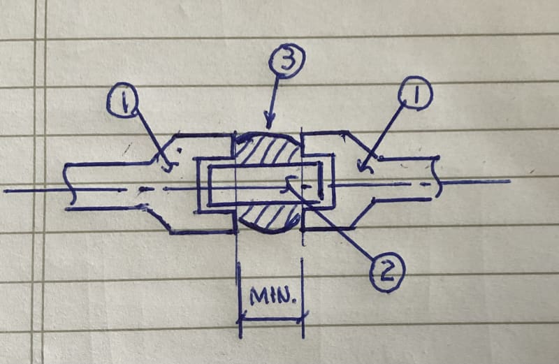
Below is a simple sketch of the “bridge weld” between two socket fitings:
1. fittings with socket joint
2. short nipple with a minimum distance between two socket fittings, may be 1/2“
3. ”bridge weld“ to cover the open gap between two socket fittings

1. fittings with socket joint
2. short nipple with a minimum distance between two socket fittings, may be 1/2“
3. ”bridge weld“ to cover the open gap between two socket fittings

Modeling this in CAESAR would give you a defensible estimate but it will be far from an accurate answer. The load calculated by CAESAR will be the reaction needed at the nipple-to-flange node to create a stress level equal to the max allowable developed in the pipe for whatever load case you are modeling. Note this does not really account for the stress riser at the threads, which is critical, except for the reduced wall thickness. The SIF for a threaded connection is a fatigue-based derating factor that will, as I said, get you a defensible estimate. Also, if this is in vibrating service, there are additional considerations. If you need a better number than CAESAR, it should be modeled in FEA. Bottom line, best to decide how accurate of an answer you need, then proceed. If all you need is an approximate number you can defend with documentation, I'd use CAESAR, then derate that value by 20% or by some other appropriate factor. This will protect you if, for example, some dude decides to stand on the flange taps, and it snaps off. Ask me how I know about that one sometime. LOLz
- Status
- Not open for further replies.
Similar threads
- Question
- Replies
- 10
- Views
- 9K
- Question
- Replies
- 12
- Views
- 1K
- Locked
- Question
- Replies
- 8
- Views
- 7K
- Locked
- Question
- Replies
- 23
- Views
- 11K
- Locked
- Question
- Replies
- 14
- Views
- 2K
