Continue to Site

Eng-Tips is the largest engineering community on the Internet

Intelligent Work Forums for Engineering Professionals

  • Congratulations KootK on being selected by the Eng-Tips community for having the most helpful posts in the forums last week. Way to Go!

Orthographic Projections for Manual Drawing 2

Status
Not open for further replies.

manster

Mechanical
Oct 11, 2023
3
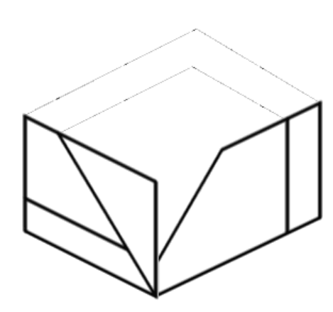
Figure below shows the two views in First Angle Projection. Draw or sketch the plan as seen in the direction of the arrow. A rough isometric sketch will be helpful for my understanding. Thank you
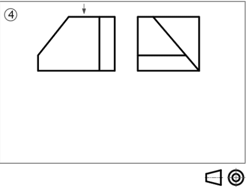
ortho_qn_uuxdha.png
 
Replies continue below

Recommended for you

An isometric won't help understand how to create the missing view, just how to answer this single problem.
 
Yes it is not asked for in the question but I have difficulty coming up with a plan view based on these two projections.
 
The drafting technique to generate the view doesn't require an isometric, but if you draw an isometric view of the two sides you have that will help you to create the isometric of the part.
 
I was taught in 3rd angle projection, sorry. What’s shown doesn’t make sense to me.
 
SW, It's first angle projection- the small cone symbol is the indicator - just move the view to the opposite side for 3rd angle.
 
Yes, I know. Just my ancient brain can’t do that switch in my head. Need to draw it on some paper.
 
SW,

Two of the other 4 views are rectangles. Does that help?
 
The solution seems incorrect.

In the front view is one area that has 5 points and a second one with 4. This means the top view will either have an area with 5 points or be a line and will have an area that has 4 points or be a line.

In the side view the same will apply to the two surfaces. Since no area in the side view has a matching vertex count, those front view areas must be lines in the side view, which means those areas are perpendicular to the side view viewing direction. All the front view area points that do not form an area in the side view will be colinear in the side view.

Use the same method to identify areas in the side view to compare to the front.

Then try connecting the dots as shown, per the above method:

trimetric_ptulbv.png


Try making some trimetric or isometric sketches and top. front, rear, LHS, RHS, and bottom views by starting with a brick shape and placing points on edges and faces and connecting them.
 
a cube cut by two inclined planes, one cutting the full width (creating the diagonal line on the side view and the horizontal line in the front view); the other cutting partially along the depth, leaving a full face at the rear, creating the diagonal line in the front view, and the larger portion of the side view.

"Hoffen wir mal, dass alles gut geht !"
General Paulus, Nov 1942, outside Stalingrad after the launch of Operation Uranus.
 
I got bored (on my spare time ...)
Screen_Shot_10-12-23_at_05.41_PM_ksi6uw.png


"Hoffen wir mal, dass alles gut geht !"
General Paulus, Nov 1942, outside Stalingrad after the launch of Operation Uranus.
 
Status
Not open for further replies.

Part and Inventory Search

Sponsor