Eng-Tips is the largest engineering community on the Internet

Intelligent Work Forums for Engineering Professionals

Outrigger beam modelling as shell or frame in ETABS 3

Status
Not open for further replies.

NewbieInSE

Structural
Dec 19, 2019
234
0
0
BD
Dear Engineers,
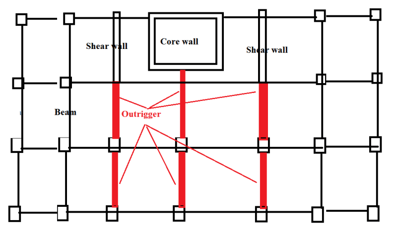
As metioned by Taranath in his book, outriggers can be of shallower depth (rather than one or two storied deep) when used in each floor. That's how we did in a project. The building is 25 storied.
Outriggers usually engage the perimeter frames in bending with core walls.
Now, I modelled such outrigger beams using frame element (24X40 inches). The outrigger spans are like of 24 ft. order. In this situation, I found that the beams don't have any axial forces in them. The building drift for wind is in the order of 1/200.
Again, I modelled those using shell element. Now the outriggers have tension/compresison forces such as 750 kips. Building drift comes down to 1/500 order.

Now, which is the correct modelling approach? Shell or frame? And are outriggers supposed to have axial loads in them?
 
Replies continue below

Recommended for you


When drifts compared 1/500 to 1/200 , probably you have used effective stiffness values ( multiply the moment of inertia with 0.35 ..) Is this true?

If you do not provide enough info. the responds would be just guess . Sometimes like a guessing game ??

Use it up, wear it out;
Make it do, or do without.

NEW ENGLAND MAXIM


Thanks HTURKAK for your participation.
The comparison is based on cracked section models, however I know that wind drift check is for 1.4 times of strength model's cracked section properties.
In one model with outrigger as frame, beams have 0.35 effective stiffness value for moment of inertia. In the other model, shell has f11, f22, f12 0.35 multiplier.
 
Modelling outrigger beams as shells causes connections at several points (along the height of the shell at its edge) of the core wall and outrigger. In the beam model, only one point is connected axially at the core wall and outrigger. Consequently, the shell may pick up normal forces and in-plane shear forces due to the way the connection is modelled (connecting at each node at the shell edge).

What the beam experiences as bending due to curvature (frame action), the shell (presumably with its thin dimension in the beam "weak axis" direction) will experience as axial deformation. Bending stiffness is much smaller than axial stiffness, so the beam deflection could be expected to be larger, as seems to be the case in your model.
 
Thanks centondollar.
Which one is more realistic in ptactice?
To me I feel like shell modelling captures the whole force transfer interaction between the shear wall and columns. Because while shells are modelled, column axial forces increase indicating that they are making a couple with the wall core. However this may not be true since I don't know which modelling best captures the outrugger behavior.

While frame is modelled as outrigger, the outrigger frame member has a bending moment of about 1000 kipft with no axial load.
While modelled as shell. It has a bending moment of around 800 kipft, with 750 kips axial force changing from tension to compression from one end to the other.
Shear force is more or less close to each other.
 
It would be useful for you to share some more information, perhaps a wall elevation showing the outrigger etc. In my experience, deep outriggers modeled as shell elements are more appropriate. Frame elements are good when span/depth ratio exceeds 3-4. For anything deeper, I would recommend shell elements.

Also make sure to not use rigid diaphragm and use semi-rigid diaphragm.
 
Outrigger_qqykws.png

The building floor plan looks like this. Couldn't post the CAD layout as I'm not on the PC having those files.
 
Span/depth ratio surely exceeds 3 or 4.

As centodollar mentioned about shell modelling, is it logical to take the benefit of continuous depth connection of the outrigger beam with wall.
 
slickdeals said:
Also make sure to not use rigid diaphragm and use semi-rigid diaphragm.
Trenno said:
No axial load in a beam element at slab level screams rigid diaphgrams are turned on.
The diaphragm is considered rigid. Would u pls explain why semirigid should be assigned?
I once read diaphragm can be considered rigid for span to depth ratio less than 3. here it is less than 3.
However, for better model response, I'll consider semirigid and check the results.
 
A rigid diaphragm means zero in-plane displacement, as it is infinitely rigid. So if the two ends of a beam are rigidly connected (constrained), there will be no movement relative to each end and hence, no axial force.
 
Status
Not open for further replies.
Back
Top