Eng-Tips is the largest engineering community on the Internet

Intelligent Work Forums for Engineering Professionals

Overcurrent protection for nonlinear heater load 3

Status
Not open for further replies.

RyreInc

Electrical
Apr 7, 2011
205
0
16
US
Hello,

We have a heater whose resistance increases substantially as it heats up, meaning its current draw decreases. If left on too long at full power (~8-12 s) it can get too hot and cause issues. Normally the heater is used in a PID loop to prevent this, but that cannot be counted on without more robust safety measures (functional safety is not feasible at this time). So I need to find a fuse, breaker, or some sort of passive device(s) that can interrupt the heating circuit if the heater stays on too long. I have looked at many time delay fuses and some circuit breakers but none have had the needed I vs. t characteristics.

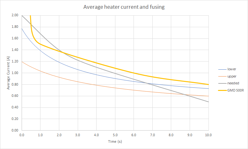
The chart below illustrates this: the blue and orange lines represent the average current vs. time for the min and max heater resistance tolerance (so the value shown at e.g. 1 s is the average of the current drawn from 0-1 s, the value at 2 s is the average from 0-2 s, etc.); the grey line is roughly what I need; and the thick yellow line is the best matching fuse I have yet found.

As you can see, the fuse stays above the blue and orange lines the whole time, meaning it will never blow.

For the grey line, which again approximates the I vs. t characteristics I need, the only important feature is that it is above both the blue and orange lines for at least the first 5s or so, and below both of those within about 10s. So it can be slightly above/below or drastically so, as long as it crosses somewhere in the 5-10s time-frame. (The portion from about 0.5-2 s where the fuse line dips below this line is ok since its still above the min/max current lines.)

Do you know of any passive devices or circuits that can accomplish this?

BTW the other option we have identified is to put a thermal cutoff switch near the heater, but this is a difficult challenge in this application.

Thanks!

image_nnqmej.png
 
Replies continue below

Recommended for you

I would use a time delay that would both cut the heater off if it stayed on too long and also send an alarm;
"PID CONTROL FAILURE"
Reducing the applied voltage will give you more time to respond.

Bill
--------------------
"Why not the best?"
Jimmy Carter
 
As IR suggests, a fuse is an over current protection device, not a temperature limiting device. There are thermal cut-outs incorporated in most consumer heaters which burn out at rated temperatures. But these operate on temperature not current.
 
As mentioned above, these little Thermal Fuses (of last resort, non-resetting) are extremely common. The selected temperature can be chosen, along with the installation location, so as to go open circuit before anything horrific happens.

31NIZd4DFXL._SX342_.jpg


Even if you decide to add a thermal cut-out (bimetallic) switch, the thermal fuse might still be a wise option.
 
Thanks everyone. I understand a thermal fuse is an option, but a very difficult one to package in this application. We are searching for alternatives that can be remotely located.

Waross, we have sufficient means of active protection, but this is for when that active protection fails. We do not have functional safety so a passive means is required in addition to the active means.
 
In electric baseboard heaters, the thermal cutoff switch is remotely located in the wiring junction box at one end of the fixture, while there's a long metal (copper?) sealed tube that runs adjacent to the heater element. If the heater sticks on because of a failure in the control system, then the heater will get too hot, the liquid/vapour in the sealed metal tube will develop a higher pressure, and that will be transmitted back to the thermal cut-off switch installed in the electric junction box that is built into one end of the overall assembly. That higher pressure will trigger the cut-off switch and turn off the heater.

If you can find an electric baseboard heater, you should be able to see one of these gadgets. Or search for the random example "Markel 57640003" to see what I'm referring to. (Apologies that I can't find a picture to link in-line here.)

If you don't have room for that, then it's hopeless... ;-) !!

 
It will take a little calculation and a lot of trial and error, but:-
Put a resistor in series with the heater and put your thermal cutout next to the resistor.
OR
Lower the applied voltage so that the heater will not overheat if left energized.

What are the implications of repeated nuisance trips?
As I understand your proposal, you intend to apply more than rated current to a fuse for a short time, hoping that the time/current fuse will save the fuse from blowing.
That is not the purpose of those curves.
Repeated overcurrent on a fuse will degrade the fuse and change the actual time/current curve.
If the methods suggested by the expert here are not acceptable and deemed not dependable enough, I don't have any faith in trying to use the fuse time/current curves in this manner.
It may work, but I wouldn't put my name to such a safety back-up system.

Bill
--------------------
"Why not the best?"
Jimmy Carter
 
Now those are some interesting ideas! Unfortunately VEBill's suggestion will not work. I am particularly intrigued by Waross's idea of the small resistor in series though, I think that may be worth pursuing.

Also thank you for the clarification on fuse usage, that is very helpful and is indeed what we are doing - we will have to change that!
 
We have a heater whose resistance increases substantially as it heats up, meaning its current draw decreases.
I actually have a problem with this statement. You would be violating ohms law with this.

You EITHER have a heater with a Positive Temperature Coefficient (PTC) of resistance, meaning as temperature increases, resistance INCREASES, or it has a Negative Temperature Coefficient (NTC) of resistance, meaning as temperature increases, resistance DECREASES. If the resistance is INCREASING with temperature as you said, then the current in the circuit would DECREASE. If the heater has an NTC (resistance decreasing), then as temperature rises, resistance DROPS and current increases. So if current is increasing, it’s because your resistance is DECREASING, not increasing.

In NTC electric heating applications for process industries, it’s often a REQUIREMENT to have a separate “Temperature Monitoring Relay” that is not part of the controller, monitoring for a thermal runaway condition. There are specific relays deigned for this, use the term highlighted above to search for them. It also requires a separate thermal sensor in the medium being heated.


" We are all here on earth to help others; what on earth the others are here for I don't know." -- W. H. Auden
 
Decades ago, I saw a horrific little heater control system where the control box contained a little heater being actively controlled. The larger remote heater was wired to have parallel action, but without any direct feedback. Extremely crude and not the slightest bit fail-safe.

Better approach (given that everything else is impossible) is to have a supervisor computer, with a hardware watchdog timer and related fail-safe heater cut-off circuitry and alarms. A clever design should be about 99.99% safe.


Hi VE
My idea was to put the monitoring resistor in series, not parallel.

Bill
--------------------
"Why not the best?"
Jimmy Carter
 
Decades ago, I saw a horrific little heater control system where the control box contained a little heater being actively controlled. The larger remote heater was wired to have parallel action, but without any direct feedback. Extremely crude and not the slightest bit fail-safe.


VEBill!!!

That is EXACTLY how 99 percent of modern electric stovetop burners are controlled today. Mine certainly are. What complete garbage that is too! Pretty quickly you find out how bad a control scheme it is. If, for instance, you turn a burner on high 100% until the pan gets a little too hot and then turn it down for the rest of the cooking you need to set the knob to 1/3. If instead you just turn the knob to 1/3 originally it will never ever reach the temperature. You will have to slowly keep upping the setting until it's 5/8 to reach the same steady state. This is because the "model" stovetop created in the knob unit never gets its housing heated up like 2 minutes of full blast does.

Keith Cress
kcress -
 
VEBill, the reason stove top burners have such poor temperature control is because they are not temperature controlled. The controls on an electric stove top are essentially power controllers, just like with a gas stove top where you modulate the gas flow, and thus the heating power of the burners. When you realize this, the behavior you describe is exactly as one would expect.

The same is true of car accelerator pedals. To control the speed of a car you use the pedal to adjust the engine power. If you keep the pedal in a constant position, you can imagine what the speed response would be.

 
There are also safety regulations for industrial ovens and heaters that require the use of over-temperature protection if it could cause a fire or other hazard. These logically are called over-temperature switches or controllers and are readily available in many forms.

The specific action you say you desire in the OP can be accomplished with a time delay relay in the power line to the heater. It could be set to turn off at 8 seconds after the power is applied, then turn back on after 8 seconds. If the power control to the heater has less than an 8 second cycle time, then the controller will be in complete control. If the power controller never cycles off due to calling for 100% power, then the relay will reduce power to 50% (8 sec. on 8 sec. off).
 
All good points.

Thread title "Overcurrent protection for nonlinear heater load" embeds arguably-bad assumptions. Temperature could run-away while the current slowly decreases (as per PTC). So the solution is nothing to do with overcurrent. In any case, overcurrent for failure modes is just a fuse or circuit breaker.

For the solution required: either there's temperture monitoring of the actual heater *, or perhaps some monitoring (and supervision) of the On time and/or duty cycle.

* One could imagine monitoring the V/I ratio to estimate the heater element resistance, thus inferring the temperature of the heater element. Monitoring the current often involves a series resistance, but that could also be accomplished with a core.


Compositepro;

Electric stovetops are not completely open loop like a car throttle.

Thermostat_ijcgii.jpg


TC_back_xscefg.jpg


They are as I described, a heater element that acts on a bimetal switch that cycles the stove-top element, using some twisted logic that that's acceptable control.

Keith Cress
kcress -
 
They are open loop as far as the burner temperature is concerned. The switch has no idea what the burner or pan temperatures are. It is a mechanical device that controls the duty cycle of power to the burner. The cycle time would be on the order of one minute. At low power it may be on for for 10% of the cycle, which means that the burner will output 10% of its full power rating. The bimetalic switch with internal heater is much cheaper than a clock motor with an adjustable cam disc, but the result is exactly the same.

You could operate a car throttle the same way, but it would not be desirable for several obvious reasons. Full throttle for one second, idle power for 10 seconds. Come to think of it, I have known some people who do drive sort of like that.

But the bottom line is that an infinite switch is a power control and in no way is it a temperature control. The name of the switch is due to it being infinitely adjustable, as opposed to the other most common approach of a switch with high, medium and low settings. It does have another operating characteristic in that it will put out slightly more power at any given setting if the ambient temperature goes down. This works to good benefit in an electric blanket controller.
 
Status
Not open for further replies.
Back
Top