Well, it's my first post though I have been reading eng-tips for a while and I appreciate the site and contributors so much! ![[smile] [smile] [smile]](/data/assets/smilies/smile.gif)
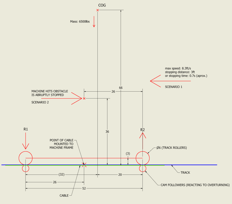
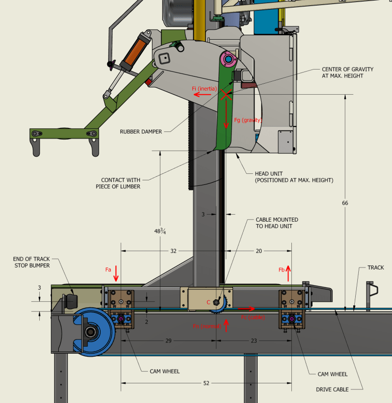
I have a machine which rides on 2 tracks, 2 track rollers per side, and is driven by cables which pull it back and forth. The sketch would be a side view of the machine.
I would like to calculate the overturning forces involved or the reaction forces R1 and R2 for 2 scenarios, to make sure the track can withstand the R1, R2 reaction forces.

[ol 1]
[li]The machine being voluntarily stopped. The machine weighs 6500lbs and has a maximum speed of 8.3ft/s. The driving cables can stop it to a stand still within 3ft (or 0.7s).[/li]
[li]The machine being forcefully stopped (an accident, rarely but possible). The machine pushes lumber and if a beam gets caught wrong and is stiff enough that the momentum of the machine will not buckle or break it, it causes the machine to halt and bounce back. The worst case scenario for where a beam would push against the machine is at the dimensions where I have the point placed on the sketch. I'm figuring for half speed in this case so 4.15 ft/s because it is restricted when sawing or pushing lumber. Also, there are dampers in the machine to absorb the impact.[/li]
[/ol]
1. For the first scenario I'm figuring for the direction of movement as shown, since R2 would be higher than R1 in this case.
I would have a gravity resisting moment of Mr = 6.5k x 66in = 429 k*in
The kinetic energy of the machine is: Ke = 1/2 x 6.5k x (8.3ft/s)^2 = 223.9 k*(ft/s)^2
Stopping force: F = Ke/stopping distance = 223.9 / 3 = 74.63 k
Moment of Inertia: Mi = 74.63k x 66in = 4925 k*in
Total Moment: Mt = Mi-Mr = 4496 k*in
R2: Mt / 20in = 224.8 k
R2 per cam wheel: 224.8 k / 2 (sides) = 112.4 k (per cam wheel)
This seems high and I would appreciate any input on my simple calcs.
2. For the second scenario I confess I'm not sure which direction to take. Some of the impact force is taken by the dampers, but the impact basically sends the machine in the opposite direction.
Any help is greatly appreciated!
![[smile] [smile] [smile]](/data/assets/smilies/smile.gif)
I have a machine which rides on 2 tracks, 2 track rollers per side, and is driven by cables which pull it back and forth. The sketch would be a side view of the machine.
I would like to calculate the overturning forces involved or the reaction forces R1 and R2 for 2 scenarios, to make sure the track can withstand the R1, R2 reaction forces.

[ol 1]
[li]The machine being voluntarily stopped. The machine weighs 6500lbs and has a maximum speed of 8.3ft/s. The driving cables can stop it to a stand still within 3ft (or 0.7s).[/li]
[li]The machine being forcefully stopped (an accident, rarely but possible). The machine pushes lumber and if a beam gets caught wrong and is stiff enough that the momentum of the machine will not buckle or break it, it causes the machine to halt and bounce back. The worst case scenario for where a beam would push against the machine is at the dimensions where I have the point placed on the sketch. I'm figuring for half speed in this case so 4.15 ft/s because it is restricted when sawing or pushing lumber. Also, there are dampers in the machine to absorb the impact.[/li]
[/ol]
1. For the first scenario I'm figuring for the direction of movement as shown, since R2 would be higher than R1 in this case.
I would have a gravity resisting moment of Mr = 6.5k x 66in = 429 k*in
The kinetic energy of the machine is: Ke = 1/2 x 6.5k x (8.3ft/s)^2 = 223.9 k*(ft/s)^2
Stopping force: F = Ke/stopping distance = 223.9 / 3 = 74.63 k
Moment of Inertia: Mi = 74.63k x 66in = 4925 k*in
Total Moment: Mt = Mi-Mr = 4496 k*in
R2: Mt / 20in = 224.8 k
R2 per cam wheel: 224.8 k / 2 (sides) = 112.4 k (per cam wheel)
This seems high and I would appreciate any input on my simple calcs.
2. For the second scenario I confess I'm not sure which direction to take. Some of the impact force is taken by the dampers, but the impact basically sends the machine in the opposite direction.
Any help is greatly appreciated!

