Continue to Site

Eng-Tips is the largest engineering community on the Internet

Intelligent Work Forums for Engineering Professionals

  • Congratulations KootK on being selected by the Eng-Tips community for having the most helpful posts in the forums last week. Way to Go!

OWSJ Bridging Design Examples 2

Status
Not open for further replies.

StrEng007

Structural
Aug 22, 2014
506
Does anyone know of a good resource that walks through the process of specifying all the bridging requirements for joists?

I'm talking about the process of specifying diagonal bracing if it's needed, construction bracing, and permanent bracing. How to determine brace forces, termination connections, checking brace angle sizes, maximum joist spacing, the works...

I have Vulcraft design guides that go into detail on how certain equations derived. What I'm really looking for is summary, flow chart, or design examples that actually shows the user how to use the design tables. Both the Code of Standard practice and OSHA requirements don't give the numerical examples.

I'm also looking for the same sort of information for how to brace additional external loads placed on joists. This will help me determine the OWSJ bridging vs bracing requirements.
 
Replies continue below

Recommended for you

The Steel Joist Institute (SJI) has some good references.

Lecture Slides from an SJI Webinar

Link to a recording of the webinar, filter topics by bridging Link

Technical Digest 2: Bridging and Bracing of Steel Joists and Joist Girders, filter topics by bridging Link

 
If you're the designer, my understanding is you can typically delegate the bridging design to the joist supplier as part of their package, there are the technical digests for Uplift and Bridging, as well.

If you provide the net uplift on the joists they can do the bridging analysis on their side, you as designer are on the hook for the bridging termination and the SJI standard specification and code of standard practice will give you the necessary force for the bridging anchorage.

You can use the bridging tables in the Catalogs to thematically show the bridging (i.e. show three runs, the center one is cross bridging but your drawings in this case are schematic and the "final bridging by joist design engineer" may change, particularly since bottom and top chord bridging/bracing need not necessarily be at the same location, particularly when there is uplift involved for lighter roofs.

Longer joists tend to have more robust bridging and also tend to have diagonal bridging at the center.
 
I'm not sure if it's just too late on a Friday, but I'm having difficulty understanding an approach by SJI (or maybe it's not limited to SJI)

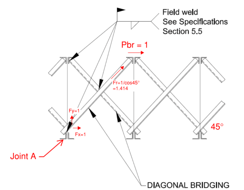
I took the following snapshots from the SJI's Technical Digest #2. When they discuss diagonal cross bracing, they mention that it's designed for tension forces ONLY.

Putting together a FBD of the brace force, where Pbr is determined by Pr/joist depth... it looks like relying on the diagonals for tension only creates forces the adjacent brace into compression. Or else the joint is unbalanced. Take Joint A for instance.

Why am I not seeing it?

Screenshot_2024-02-02_161232_pkqd0m.png
Screenshot_2024-02-02_161324_ciisev.png


Furthermore, it says that horizontal bridging is design for compression only. Unless the sign is changing along the member length, I don't understand how it's compression only, when in reality joist displacement can cause (drag) on the adjacent horizontal brace.

Can someone help me understand this, please?
 
This is perhaps "tension only bracing" in the same sense as the old diagonal bracing, one neglects the compressive strength of the bridging. Now, as to your actual question, yet, it seems there's an imbalance. The joists generally deflect downward or upward equally, and my impression is diagonal bridging is most typically seen at the mid-span and is partly OSHA mandated for erection safety circa 1998.

I say 1998 because my Vulcraft 1998 Joist catalog has a big note on the cover about bridging.. It if's an OSHA element it's perhaps not rigorously math but a required size or area?

Yea I'm not finding what I'm looking for, but this looks nice and distracting:
Ok, I think this is what I was looking for, the year sounds about right - plus Beaulieu sounds familiar as well, I'm not sure that's "on point" for this topic, but to me that's where the death of the compression force being used in diagonal bracing for steel construction occurred.

I'd encourage you to contact a local joist supplier. They may be able to refer you "up the chain" to the engineering manager for the area and they'll have more insight.

The bridging I've seen in the field is pretty small section angles, so they'd offer limited capacity in compression even if the weld/bolt were able to transfer the load.

I also wonder if the bridging isn't designed exclusively for a horizontal force, particularly the diagonal bridging as that's (in my mind, at least) for erection stability, note that there's a gap between the two top chord angles so the load has to go into the one top chord angle, maybe up into the deck, then back into the other angle? That seems like the stiffest path, otherwise the top chord has to take the sideways load somehow to a panel chord or a filler plate?

Regards,
Brian
 
I've read through the SJI specification, code of standard practice, and technical digests on specifying joists and bridging. None of these documents actually discuss the method to determining the forces in the bridging members via structural analysis. All the requirements follow some quasi prescriptive method and there are equations that back up these methods.

Does anyone have a structural analysis example of how forces in diagonally braced joists are determined via free body diagram, truss analysis etc.?

This would include:

1. Diagonally braced joists without horizontal top/bottom bridging.
2. Diagonally braced joists with horizontal top/bottom chord bridging.
3. Diagonally braced joists with bridging terminating at an end joist.

 
I generally used horizontal bridging only with X bridging every 50' to take the tension load into the top chord area, and anchored to the top at the ends...

-----*****-----
So strange to see the singularity approaching while the entire planet is rapidly turning into a hellscape. -John Coates

-Dik
 
Why?

The bridging design is under the responsibility of the joist design engineer.
 
Through understanding how this works, it'll allow me to determine how to reinforce joists for new RTU loads placed on the the roof.

I'm trying to rationalize that a lateral force that works it's way into the bracing mechanism would shed light on how an external lateral force would travel the same path.

Bear with me, I might be going about this completely the wrong way. I understand the combination of the diagonal bridging and horizontal bridging to create an 'inverted' braced frame. The only issue is, where does the lateral force go? I don't want to assume that 100% is absorbed by the roof deck. Ideally, I'd like to the the lateral load work it's way back into the joist as a vertical load, but my analysis is proving that the lateral load either has to be put into the roof deck, or it has to run down the entire line to the bridging terminus point (ie the exterior wall or a joist/beam stiff enough to take the lateral load).

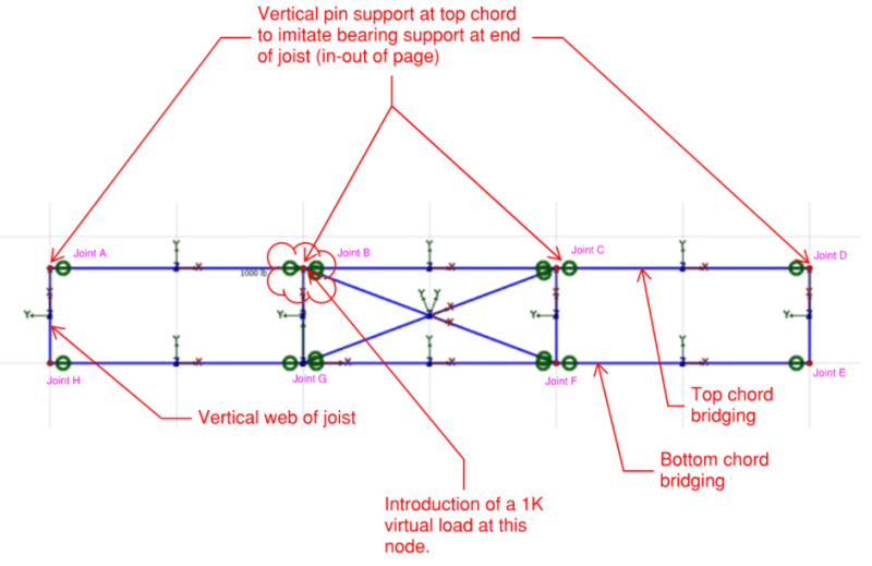
To get this conversation moving, I've provided a snapshot of my attempt at modeling this scenario. As expected, the model yields unbalanced reactions.
The Joints at A, B, C, D are supported in the Y-direction. While this may not be true at the location in the field, the joist supports the vertical loads (maybe it should be modeled as a spring). I'm trying to see how I can get the lateral load (introduced at Joint B as a 1K virtual load) to work it's way back into the share of vertical supports.

Is there a way to do this without having continuous top/bottom chord bridging down the entire line.

Screenshot_2024-02-06_1050271_h87aon.png


Another thought I had is: Does the horizontal top/bottom chord bridging and diagonal bridging create a faux 'perpendicular truss' to the span of the joists?

dik said:
I generally used horizontal bridging only with X bridging every 50' to take the tension load into the top chord area, and anchored to the top at the ends...
Do you mind illustrating how you calculate this?
 
...as you show, but the horizontal bridging lengths can be several hundred feet long. I add cross-bridging at about 50' intervals.


I had a spreadsheet that I developed. The SJI has an excellent *.pdf presentation, noted above, that illustrates this that is more current. When I developed the spreadsheet... it was about 40 years back and there are many improvements since.


-----*****-----
So strange to see the singularity approaching while the entire planet is rapidly turning into a hellscape. -John Coates

-Dik
 
I take your point, the load path isn't explicitly handled. It's going somewhere successfully or it'd all fly off the planet or collapse to the ground, so there's a load path.

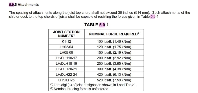
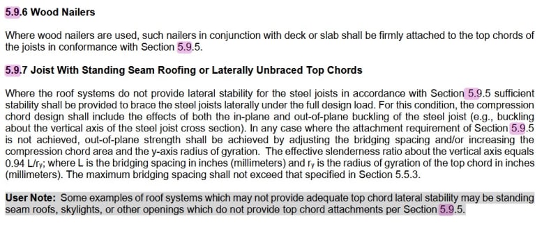
The bridging, to me, is there for erection stability. The SJI requires the top chords of the joists be secured at 36" o.c. to something, i.e. the metal deck, typically. If it's a standing seam roof this dramatically changes what the bridging does and it's a big "let us know" item for the joist suppliers. I think they will still do bridging but then my question (as EOR) is where's the roof diaphragm, which means some manner of horizontal truss/alternative and it's still "mine" as EOR. I suspect their bridging is intended for gravity loads in that scenario and it's not going to provide any worthwhile diaphragm values.

While it is technically possible for gravity forces to go into the bridging, first you have the bolt hole versus bolt diameter, both ends, (unless it's welded?) and second you really need differential deflection between two joists to produce that force via bearing on the bridging angle, the bridging angle, if designed for tension only, has very little compression resistance, as well as the eccentric effects of the connection making it even weaker, and these aren't massive angles to start with, I'd expect them to buckle under even fairly trivial loads. The model ironworker, who isn't supposed to be sitting on the joist at mid-span, is 250 pounds. So the bracing force that goes into the bridging is less than that, provided adequate (tension) stiffness in the bridging is provided.

Uplift is a different creature, but the bridging in that case is there to brace the bottom chord, not exactly part of a fully resolved load path (perhaps).

Admittedly, I have not done a deep dive into bridging analysis or design, I focus more on the anchorage of the bridging to the exterior wall. They give a force, I provide an attachment.

Regards,
Brian
 
Other than this being a somewhat academic exercise I think you're getting a little bit lost in the weeds. Bridging (horizontal and diagonal) are focused on erection stability (keep the joists from rolling over when workers are up there) and has no intended effect on gravity loads/load sharing/diaphragm action as far as I'm aware. I've never considered bridging in any sort of joist analysis other than providing anchorage for the bridging. There's also uplift bridging but it's a bit different as lexpatrie noted. All of this is designed and provided by the joist supplier. The most we'd show on our drawings is just a visual representation of the bridging for new builds, and nothing for existing buildings.

Check section 5.5 of this doc (if you haven't already). [URL unfurl="true"]https://steeljoist.org/wp-content/uploads/2021/05/StandardSpecs_K_LH_DLH-Series_0820.pdf[/url]
 
dold said:
Bridging (horizontal and diagonal) are focused on erection stability
Understood. The questions I brought up in the OP are watered-down versions of the sorts of requests I'm getting for analyzing existing joists.

What's really going on is that I'm trying to determine the best way to rationalize the introduction of new RTU's and roof top screens on existing joists. The gravity component is not so much of a concern because I've already established, what I believe, is a good rational approach. Where I'm concerned is the introduction of lateral load since some of these roof top configurations are 1) tall, 2) located in high wind areas.

The reason I started picking at erection bridging and construction bridging methods was to understand how the joist is acting when it cannot rely on the existing roof deck. Don't get me wrong, my roof deck IS going to be providing lateral bracing to the existing joist top chords... I just don't know how much I can rely on it with individualized lateral point loads. My concern is the fact that these roof top features could 1) create some sort of localized lateral displacement of the top chord. or 2) create some twisting of the joist.

Since I have to start somewhere, I figured I'd try to understand the bracing mechanism.

dold said:
I think you're getting a little bit lost
Yeah, I'm often trying to figure out these things that my peers so joyfully don't consider. That's why I come here to talk with you all!
 
This may be of some use - Standard specification for K, LH, and DLH joists as of 2020.

SJI_Standrd_Spec_top_chord_attachment_pl2nxy.jpg


If need be you can track it backwards through the 75 year catalog and tables to see what the requirements were around the time of original construction, if that can be reasonably established via the property assessor or satellite imagery.

I'll add the language about standing seam as well.

SJI_standard_spec_Standing_seam_jvb8jq.jpg


Incidentally, farther up in that section it has horizontal bridging at l/r of 300 and diagonal bridging at l/r of 200. The way the second item is worded, 5.5.2, the l is the full length of the bridging. The potential bolt in the middle of the "X" is not counted as a brace point or determination of slenderness.

I guess the point here is anything beyond the required strength and spacing for the bracing of the top chord (i.e. not the bridging, the metal deck connection) would potentially be available for restraint of "other" lateral loads.

As to the original problem, lateral loads from RTUs and unit screens, look at Designing with open web steel joists, Fisher, there is some treatment of lateral loads across the joist from a guy wire anchorage. I thought the second edition had some designs for RTU screen attachments as well.
 
lexpatrie,
The Vulcraft reference (Designing with Vulcraft Steel Joists...) you mentioned was so helpful and has pointed me in the direction of another Technical Digest that might be worth purchasing. I actually have a hardcopy of it but didn't realize there was a special topic on joist reinforcing.

What's interesting is the comparison between Vulcraft's method of analyzing the joist vs SJI Technical Digest #2. One primary difference I noted was:

SJI Method
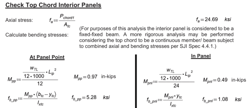
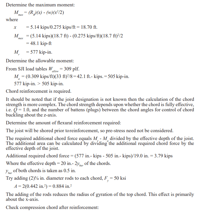
•When SJI checks the capacity of the chords, they first check the fa/Fa unity of the chord where fa = Pchord/A (where Pchord is determined from the applied moment divided by the joist chord moment arm)
•Next, they will determine the fb = Mc/I in the top chord interior panels (see snapshot below), then combined fa and fb is then checked via unity equation (fa+fb)/0.6Fy

Screenshot_2024-02-07_165159_yewvrq.png


Screenshot_2024-02-07_165218_ue5qhg.png


Vulcraft's Joist Reinforcing Method
•For handling the moment capacity of the joist, only the fa/Fa ratio is considered. They don't actually add any contributing bending stress in the top chord itself.

Screenshot_2024-02-07_165316_profxk.png


Correct me if I'm wrong, but I find this analogous to:

•SJI is applying P/A +M/S, where the contributing bending stress is due to the fact that the chords are considered continuous through their span?

•Vulcraft is treating the joist as a truss with pinned nodes, and thus ignoring the stress contributed from bending. Here the M/S is eliminated from the analysis and we're only looking at the axial force in the chord itself.
 
Correction to what I was saying:
•SJI is applying P/A +M/S, where the contributing bending stress is due distributed loading applied to the top chord between panel points.

•Vulcraft is ignoring the stress contributed from bending of the top chord between the panel points. Here the M/S is eliminated from the analysis and we're only looking at the axial force in the chord itself.

Granted the fb stress is much less than fa, I'm not sure why Vulcraft is taking that approach.
 
I'm not positive it's "Vulcraft's" approach, I think Vulcraft published it, the content is James Fisher and a few others? None of those guys is actually at Vulcraft last I heard. Vulcraft and the other Steel Joist fabricators, beyond the occasional "eh that's okay" or a repair drawing for a truss, don't engage in the reinforcing design of open web steel trusses.

You're probably using Vulcraft as shorthand for the book (there was a hardcover at one point, I have a hardcover second edition of Fisher/Van de Pas), versus the SJI being the technical digest.

 
Yes, I'm referencing both the 2nd edition and 3rd edition of the design book you mentioned.

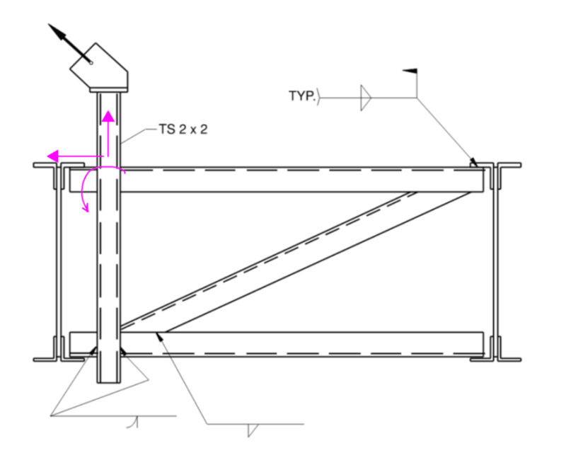
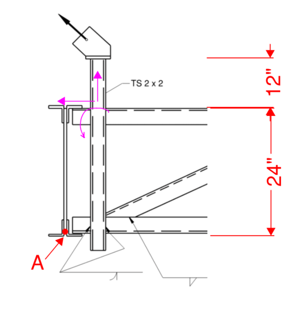
From the 2nd edition, pg. 83, how do you resolve this load path? If the joist depth is 24", spacing 60", and the load is 1K (45° at 12" above top of joist), what forces would you get in your framing members and how do we get resolve this to the overall building structure?

The y-component would put uplift in the joist on the left (let's call it Joist A). However, there is an eccentricity to this load since the horizontal angles are only attached to one side of the flange.
The x-component looks like it would be dragged out through the roof sheathing, assuming we have an adequate diaphragm here. However, it we didn't then what's the path (I'm assuming the top horizontal bracing would need to go all the way to the outside wall)? There is also a rotational moment to be resolved.

I'm trying to determine how to handle this load path via a simple FBD.

Screenshot_2024-02-12_153106_tz98a2.png


If we try cutting this and solving via method of sections (moment at A), we have (4) unknowns:
•Fx top horizontal brace/or dist. into roof diaphragm
•Fx bottom horizontal brace
•Fr diagonal brace
•Fy vertical component that goes into the joist.

Screenshot_2024-02-12_154913_ocvqiu.png
 
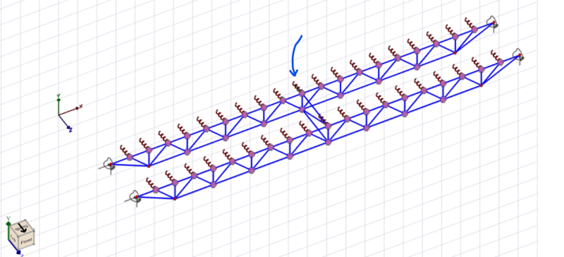
In an attempt to better understand this (emphasis on the attempt part), I created a basic model with the introduction of a 1K Vertical point load and 1K lateral point load at the node indicated with the blue arrow.

Screenshot_2024-02-13_113240_jzpbzz.png


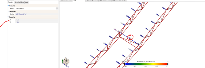
In order to keep my model happy and have no lateral reaction at the end of each joist (Z-direction reaction at joist seats), I had to create some soft of lateral support along the top chord of each joist. A spring support was placed at each node, which represents the presence of a metal deck diaphragm.

The first joist (the one that takes the initial later load) takes 500lb of force from the combined reactions in each spring. The remaining 500lb travels through the horizonal brace and the distributes into the springs that supports the second joist. The diagonal and bottom horizontal are zero force members in this situation.

Screenshot_2024-02-13_113346_c7scz8.png


Is this to say, that all lateral forces will directly distribute to the diaphragm and there is actually no need to create a triangulated brace at the introduction of individual point loads?

Keep in mind this was only a 1K point load. At what point do I have to worry about locally tearing the diaphragm?

I really wish there were some design examples that could shed some light on this situation because the more I try to break it down and understand it, the farther I'm getting from my original assumptions on how this works.
 
If you haven't seen this yet, (and I'm not really answering your question), there's a discussion of bridging (for uplift) around the 33 minute mark.


Wind Design Considerations for Joist and Joist Girders, 2017 Holtermann and Jeudemann

As to your force question, why not disconnect the top chords at the angle brace frame to force the loads elsewhere? Remove the springs just at those nodes. If the diaphragm can't take that load, the analysis will show you where it goes, (intuitively I'm expecting a download and an upward load on the joists).

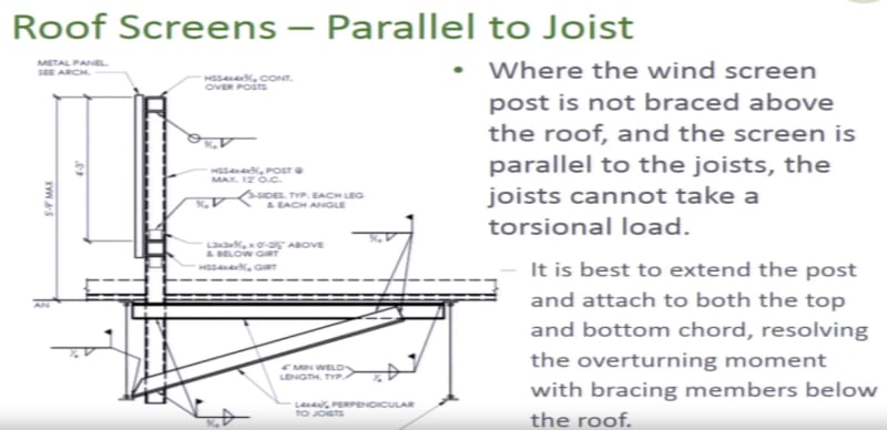
Roof_screen_uyhhbt.jpg
 
Status
Not open for further replies.

Part and Inventory Search

Sponsor