Continue to Site

Eng-Tips is the largest engineering community on the Internet

Intelligent Work Forums for Engineering Professionals

  • Congratulations KootK on being selected by the Eng-Tips community for having the most helpful posts in the forums last week. Way to Go!

Parallel beams bracing 8

Status
Not open for further replies.

Italo01

Structural
Sep 4, 2021
169
Hello Guys,

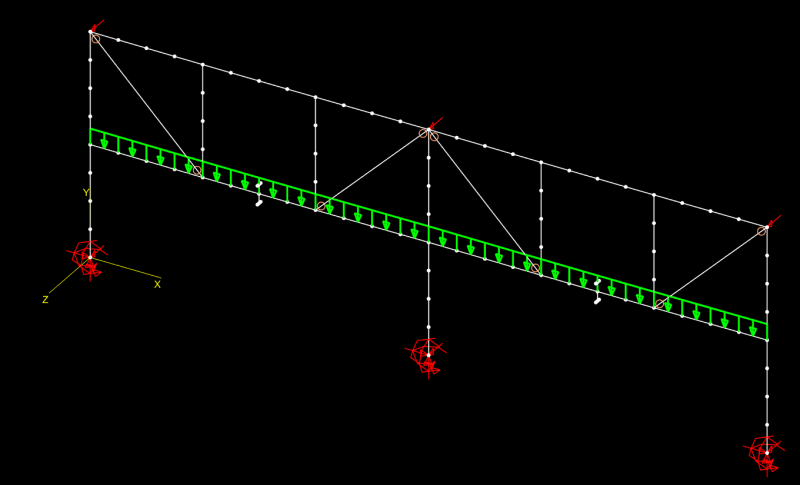
I have the following frame( Showing only the necessary part of the structure for the understanding of the problem). The Span is 9,00m(30ft) and the intermediate beam is suporting non-structural masonry. In order to increase the stiffness of the frame, share a part of the load of the intermediate to the top beam and give better suport to the masonry wall, i introduced the green ties. My question is, if i utilize rigid connections, the ties will brace the beams for LTB(Torsional bracing)?
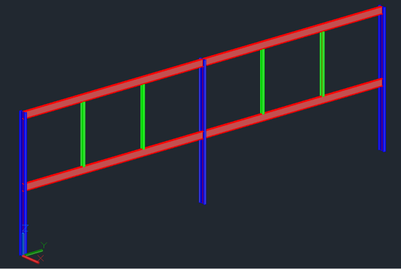
Frame_jwojzr.png


Is there a document that deals with this kind of bracing?

I don't think that it won't be as effective as a traditional bracing where the beams are on the same horizontal plane but may be sufficiente.

Thanks in advance.
 
Replies continue below

Recommended for you

The same Yura paper that deals with bracing in general; you just have to determine how your setup satisfies the requirements.

I'm going to go with it won't satisfy stability bracing. Even if you make those connections rigid, you still have what appear to be skinny open sections which are notoriously bad for torsion. And the only way this works is if they are provide torsional bracing to one another.

One benefit is that any tension load in your ties is being applied below the neutral axis of the top beam, and so wouldn't really contribute to LTB. But that'll be minor.
 
Like phamENG said, it doesn't look promising.

In AISC/Yura terms, you would be trying to use the green members as torsional point braces. Distortion of the web of the red members would play a big part in the calcs, so you would probably need to add full-depth stiffeners to the red member web at the green member connection locations.

In the AISC Specification, torsional point braces are covered in Section 6.3.2a. They might be called "discrete torsional braces" in the Yura "Beam Bracing" paper phamENG referred to.
 
Thanks PhamENG and 271828. I know the Yura paper but i was hoping to see a paper dealing directly with this setup( I recognize the laziness on my part!).

Before trying to calculate by hand, i created three Mastan models to verify the beam resistence and the models did show a considerable increase in the resistance. The models still don't include the flexibility of the connections, so i will do this next, for both the stiffened and unstiffened connections.
I Introduced partial yielding and initial imperfections as described on the stability fun guide of Mastan.

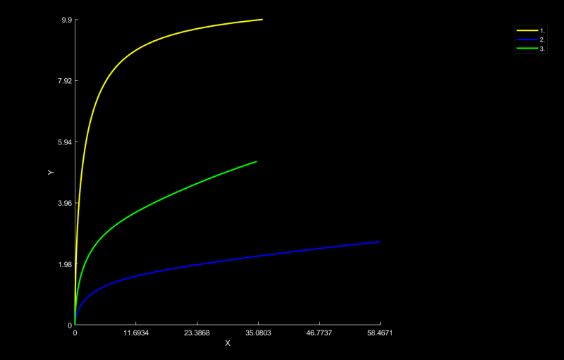
In the first model, the intermediate beam acted alone(Blue Curve), while in the second, the tie was connecting the beams by pins(Green Curve), resulting in a 96% increase that is close to the 100% increase expected and in the third model, the tie was connecting the beams by rigid connections, resulting in a 267% increase(Yellow Curve)

FrameCurves_f3slvr.png
.
 
I'd wonder if perhaps your Mastan model is more significantly impacted by the intermediate "support" conditions provided by the hangers rather than any bracing they may provide. I could see the hangers significantly impacting the moment gradient and potentially at least in the fixed model developing full moment reversal which if I recall from the Yura paper can significantly increase Cb.
 
Celt, this effect is introduced on the model where i pinned the ties, or hangers (Green curve). I think that it will behave as a lean-on bracing, what is verified by the fact that the load is almost doubled.
 
LTB is a concern on the compression face of beams. Your unbraced length of the top flange may be ok to mitigate LTB, but your hangers will create a negative moment and compression in the bottom flange of your beam. On the bottom flange, there is nothing to prevent or resist LTB.
 
In a pinch, you can add cover plates to either side of the web (welded from flange tip to flange tip) and effectively make a tube. You could also just swap out your W-flange for a tube. It would limit the effects of LTB.

"We shape our buildings, thereafter they shape us." -WSC
 
Italo01 said:
Before trying to calculate by hand, i created three Mastan models ...

Very cool. I hope you'll say how the Mastan results compare with the AISC/Yura torsional bracing results.
 
I agree with Celt here. I think the increase in strength has more to do load sharing and changes to C[sub]b[/sub] than it does with bracing.

There may be some bracing provided...if the bottom beam starts to buckle laterally, the top flange (assuming top flange in compression) tries to move down and to the side. Even with pins, there is a limit to the range of motion available to that top flange based on the length of the brace and the stiffness of the beam above. But I have a hard time believing it's enough to make a difference in the real world.

Please do post the difference between your model and the hand calcs based on Yura and the AISC appendix. Also look at the allowable loading assuming your hangers are supports for the bottom beam (or whichever beam has more deflection if not connected)
 
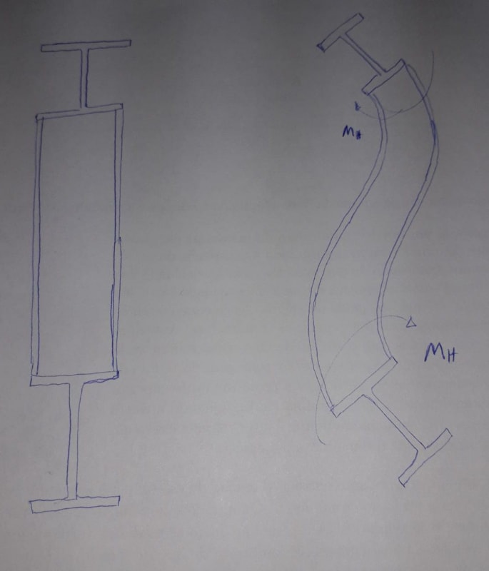
MotorCity, i think that you didn't understand how the bracing is working. The following image shows the behaviour that i'm considering. The Hanger will share the load with the top beam but if the beams fail by ltb, the hanger will bend out of plane. The hanger resists and applies a reacting moment, which a called Mh, that reduces te torsion on both beams. If the hanger is stiff enough, the will remain vertical and will displace only laterally, which occurs for a higher load. I'm not considering that the hanger braces the top chord laterally.

Torsional_Bracing_skl4h9.jpg


PhamENG and Celt, both effects occur. To show this, i did create a fourth model and i'll try to describe better the results below.

A - First i'll show the BMDs of each model for 1st order analysis and a uniform load of 1KN/m:

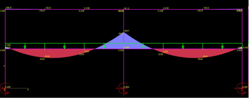
A.1 - When the beam is acting alone:

Frame1_rq5mfh.jpg


Mmax=9,437KN.m
Cb=2,03

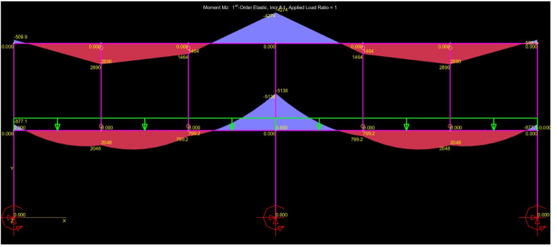
A.2 - When the beams are pin-connected to the hangers, the BMD for 1st order elastic analysis is the following:

Frame2_xoxlh6.jpg


Mmax=5,138KN.m
Cb=2,16

The maximum bending moment reduced 45,6% and Cb increased 6,4%, so the load increase 95%, consistent with the previous 2nd order inelastic analysis.

A.3 - When the beams are pin-connected to the hangers in-plane and rigid out-of-plane, the BMD is equal to A.2, so if not for some bracing effect, the failure load should be equal to A.2, but the 2nd order inelastic analysis shows a 75% increase to model A.2 (240% increase to model A.1)

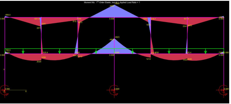
A.4 - When the beams are rigidly connected to the hangers, i obtain the following BMD:

Frame3_vlmr3c.jpg


Mmax=4,823KN.m
Cb=2,16

The 2nd order inelastic analysis show 6,5% increase to model 3, consistent with the 1st order analyis. This small increase occurs because the hangers absorb a share of the bending moment of the beams.


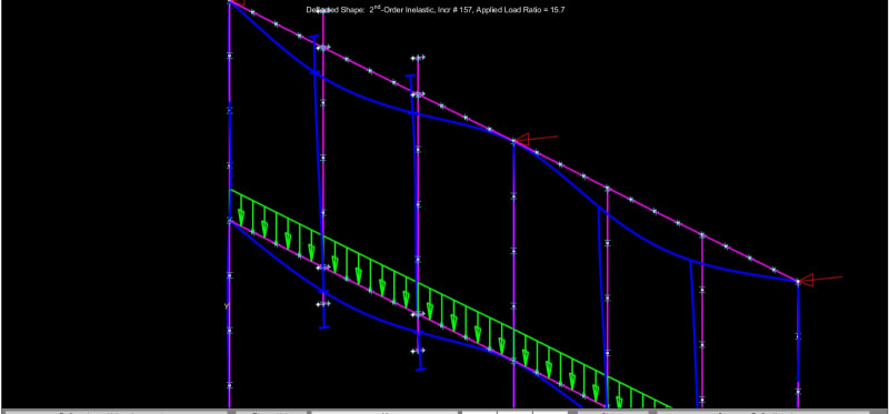
B - The deflected shape that i obtain with the 2nd order inelastic analysis show the beams almost vertical at the intersection with the hangers, which confirms that these act as torsional bracing

Frame4_bzvxor.jpg
 
I would agree with 271828 that AISC App 6.3.2a is a great resource for calculating if the braces are stiff enough to act as a torsional brace. The one thing that I would be concerned about where the torsion is going. I know for lateral bracing (AISC App 6.3.1) the lateral load needs to have a load path to a LFRS or else it does nothing, however I'm not sure about torsional braces.
 
You're sort of forming a Vierendeel truss with it that way, and as you can see your "top chord" is buckling laterally.

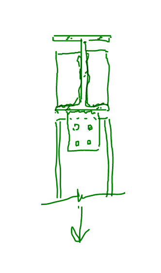
For your sketch in the first image, I would only buy that if you put stiffeners in. Preferably a split tube (same size as the hanger) that gets welded into the web and to the flanges.

Perhaps it is possible to set up a torsional bracing system this way. How does it compare to the hand calcs?
 
Thanks, PhamEng.

I'll check all the hand calcs now. This morning i was at a company meeting and could not work on the problem. I have one more question regarding torsion boundary conditions. I intend to connect the beams to the column using end plates. In this case, with respect to warping, this connection will be continuous or free?

It depends on whether the connection has a stiffener?
 
Correct. If the end plate connection is sufficiently stiff to act as a fully restrained moment connection, I believe it would do an adequate job of restraining warping in the beam as well.
 
PhamENG, because of your comment on the Vierendeel truss, i had an insight and decided to change the concept. I talked to the contractor about the possibility of putting some HSS diagonals like shown below and he said that could bulid the masonry this way. So i decided to change to this truss configuration.

In this new configuration, i substitued the W-Shapes for HSS shapes with strong axis horizontal. Both are subjected primarily to axial load, while the bottom one to flexure-tension, but the bending is continuous with support at each 1/3 span, so values much below the former solution.

MastanFrame_kvodcv.png
 
I agree with 271828's comments.

You'd likely need stiffeners on both red beams to increase the distortional stiffness of the web.
Additionally, the braces would have to withstand a moment of 0.02MReq (depending on which codes you are using).
This brace moment would then have to be divided by the green span length which would cause equal and opposite weak axis forces in both of the red beams. I imagine this would have a significant impact on the design.
 
Italo01 said:
My question is, if i utilize rigid connections, the ties will brace the beams for LTB(Torsional bracing)?

Yes, that's an excellent bracing system and you're pretty much nailed the concept. I'm afraid that you've been led astray pretty badly in many of the previous posts that question your approach here.

Italo01 said:
I don't think that it won't be as effective as a traditional bracing where the beams are on the same horizontal plane but may be sufficiente.

Toss in some dirt simple stiffener detailing, as 271828 suggested, and I feel that your system would be as effective as when the beams are in the same horizontal plane.

Italo01 said:
Is there a document that deals with this kind of bracing?

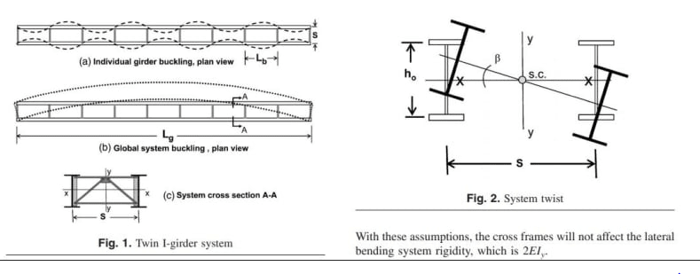
Your system bears great similarity to how diaphragm bracing is used for twin bridge girder buckling, per the sketch below. And I'd be tempted to adapt similar checking procedures. That, combined with your MASTAN work, would give me great confidence in this system.

Moreover, pretty much ever truss chord the world over is torsionally braced by its webs in exactly the same way.

Italo01 said:
I talked to the contractor about the possibility of putting some HSS diagonals like shown below and he said that could bulid the masonry this way.

Don't do that. It's unnecessary if the beams are already designed properly and it will make the wall more difficult to construct. You had the right idea straight out of the gate.

C01_kweakh.png
 
As far as your stiffener detailing goes, it can be as easy as the sketch shown below.

Italio01 said:
I have the following frame( Showing only the necessary part of the structure for the understanding of the problem).

Is there not a roof diaphragm that will brace the upper beam laterally?

C01_xjx9ux.png
 
Kootk, thank you so much for you advice.

i was very confident about my approach and is good to see someone so experient and knowledgeable as you to confirm it. With respect to the second approach, i changed it not because i didn't feel confident about the first approach but because i could reduce considerably the weight of the steel, since the moments are much smaller and the stiffness is much greater.

I know that its going to be more difficult to construct the wall and maybe you'd think that its not worth it to the client the cost offset but i assure you that in my region it is. I live in Brazil where the cost of Steel is twice the cost in usa and where labor cost is 1/5th ot the usa.
 
Status
Not open for further replies.

Part and Inventory Search

Sponsor