Continue to Site

Eng-Tips is the largest engineering community on the Internet

Intelligent Work Forums for Engineering Professionals

  • Congratulations KootK on being selected by the Eng-Tips community for having the most helpful posts in the forums last week. Way to Go!

Pedestrian truss "pony truss" 10

Status
Not open for further replies.

Gus14

Civil/Environmental
Mar 21, 2020
186
My boss wants a pedestrian truss like shown in the attached picture to support 6 meters long floor beams {W 5*16). He wants the pedestrian bridge because it can serve as a hand rail and not decrease floor clear height. I did the analysis and found that the maximum axial load in the top chord 100 kn in comp and in the bottom chord 100 kn in tension. I chose section HSS (2*2*3/16) for top, bottom chords, diagonal and verticals FY IS 50 ksi. After revising the AASHTO GUIDES for pedestrian bridge i found that I need to weld another ( HSS 2*2*3/16 ) to prevent top chord buckling and be conservative.

1) in the ASSHTO guides stats the following : the connection to the floor beam to the vertical shall not include the HSS chord member, i.e. the vertical and the floor beam shall not be connected to different sides of the HSS chord.
SO WHERE SHOULD I PUT THE BOTTOM CHORD IS IT POSSIBLE TO PUT IT ON TOP OF THE FLOOR BEAMS AND HOW FROM THE INSIDE OR OUTSIDE or in between verticals ?

2) I really have no idea how to design the gusset plate connection any simple reference would be very appreciated. And any conservative answer is also welcomed.
 
 https://files.engineering.com/getfile.aspx?folder=ad7a82ec-4530-4f6b-8635-56f57c88f11c&file=2.pdf
Replies continue below

Recommended for you

Where are the floor beams - transverse to the truss, in what spacing? You have selected an all-tube design, use all weld connection, as gusset application is not practical for this situation. Or, design a Vierendeel truss instead to save the weld works.
 
The floor beams are spaced at (.4 meters) same spacing as the truss verticals. I'm worried that an all weld connection might not be enough.
 
1) I'm not a bridge guy and I'm not great with AASHTO so take my advice with a grain of salt. If you provide the relevant AASHTO provisions and issue year, I'll check 'em out though.

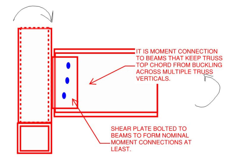
2) Recognize that is the moment connections between your truss vertical and your beams that are stabilizing your truss top chords against buckling. It sounds to me as though you've got that part.

3) Because of #2, I suspect that the point of the AASHTO provision that you mentioned is to prevent excess flexibility in the moment connection mentioned in #2. Too much flex in too many HSS walls for anybody's liking.

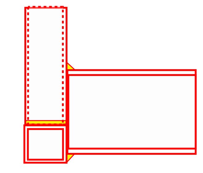
4) I think that raising the beams a bit above the bottom chord as shown below might be a practical solution. It's not a super robust moment connection but, at the scale of this structure, I feel that it would be adequate if you can find some way to evaluate the joint flexibility rationally.

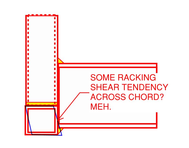
5) I do think that an all welded connection would be enough if you make it directly to the verticals rather than the bottom chord.

C01_lo56ge.jpg
 
Frankly, again at the scale of what you're contemplating, I feel that this would be adequate as well.

C01_za0jk6.jpg
 
Gus14 said:
My boss wants a pedestrian truss like shown in the attached picture to support 6 meters long floor beams {W 5*16).

Try proof reading your own text. The floor beams can't be 6 meters long. They are the beams which span between trusses.

Gus14 said:
SO WHERE SHOULD I PUT THE BOTTOM CHORD IS IT POSSIBLE TO PUT IT ON TOP OF THE FLOOR BEAMS AND HOW FROM THE INSIDE OR OUTSIDE or in between verticals ?

There is a cross section shown in the AASHTO document showing the bottom chord of the trusses below the floor beams. Why don't you do something similar?


BA
 
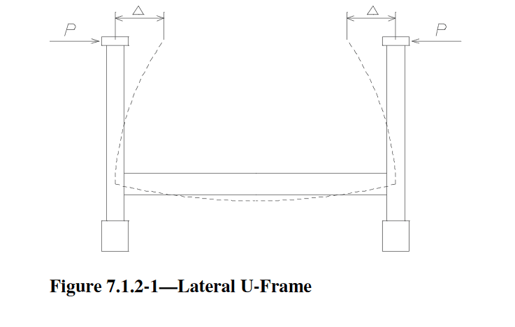
Gus, I think that the code is discouraging that type of connection if you are looking to rely on U-frame stiffness, which may be useful for you.

It would need to be a welded joint, not just a shear tab if you need a moment connection, and thus, U-frame action.
 
 https://files.engineering.com/getfile.aspx?folder=878aad13-ba5f-4963-84c0-81736bdf995f&file=SKM_C55820070608060.pdf
This is the cross section in the AASHTO guide.

image_mml8di.png


BA
 
Thank you everyone for Info.
the structure is not a bridge. sorry for mixed terms.
The floor beams which spans between the trusses are 6 meterr long ( I don't see anything wrong with that )

I somehow did not see the aashtoo section. But still I do not want to decrease floor clear height. So I am thinking about doubling the top chord area and going with kootk details ( This way I wont need the fixity as much)
 
I'm worried that an all weld connection might not be enough.

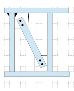
Why not? Below is a suggested detail. The gusset is attached to the slotted HSS using thru bolts, I think AISC has similar detail/examples.

Can the floor beams attached to the verticals using simple shear plate connection?!

image_nvfden.png
 
In number 2 I was not talking about the floor beam to the vertical connection(sorry for any confusion). I was talking about all the other connections between members.
 
Gus14 said:
the structure is not a bridge. sorry for mixed terms.
The floor beams which spans between the trusses are 6 meterr long ( I don't see anything wrong with that )

If it's not a bridge, what is it?

Six meters is a long span for a 5Wx16.

BA
 
Gus14 said:
So I am thinking about doubling the top chord area and going with kootk details ( This way I wont need the fixity as much)

As you've sketched your truss, there's no way to get around one or more of your vertical post / floor beam frames having to stabilize the top chord. As such, I'd recommend embracing that stability mechanism in some fashion rather than trying to circumvent it.
 
Well the spacing is only .4 meters so assume the Dl is 3 Kn/m2 and live load is 3 Kn/m2 then the sum factored is 8.4Kn/m2 then multiply by .4
and thats only 3.4 Kn/m run so the moment is only 15 Kn.m so its not really that much
 
To an extent, you may want your floor beams stiff enough to be restraining top chord lateral movement rather than encouraging it.
 
When I used aashtoo formula it relied o the inertia of the floor beam so i will subtract the area that is lost due to the existance of the bottom chord and see how much fixity is lost and adjust the top chord area accordingly. maybe double it by welding another HSS on top of it.
 
This is my worst client by far. He made me redsign his structure 3 times he doesnt want to decrease the height more than 14cm (5.5 inch) and doesnt want to pay much so I need to count on every Sq inch of my structure. [upsidedown]
 
Why not just cantilever the columns up above the deck and then you have a restraint to your top chord every 6m. Size the top chord for buckling accordingly.
 
MIS's concept may well have legs. For reasons of contructability, I'd probably switch the truss spans to simply supported spans and ditch any continuity.
 
Status
Not open for further replies.

Part and Inventory Search

Sponsor