Continue to Site

Eng-Tips is the largest engineering community on the Internet

Intelligent Work Forums for Engineering Professionals

  • Congratulations GregLocock on being selected by the Eng-Tips community for having the most helpful posts in the forums last week. Way to Go!

PEMB: 240k Kickout Tie-Beam 5

Status
Not open for further replies.

UTvoler

Structural
Oct 7, 2010
49
Hi all! I am working on a PEMB with a 200' clear span, with factored horizontal reactions of 240kip at the baseplate. I am really struggling to get this magnitude of a shear reaction into the the pier and then transferred into the tie-beam. To make things extra fun, I have two frames where my tie-beams will intersect pits in the floor, and so the tie-beams want to drop down 24" below the top of the slab, which makes the pier ACI anchor rod checks impossible without an 8-ft square pier (I also tried the strut-and-tie approach with no luck).

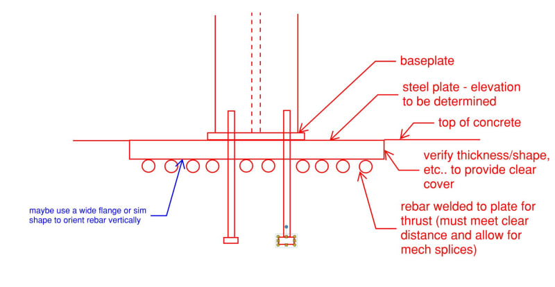
All that aside, my "typical" tie-beam that I am somewhat comfortable with is 24"x16" concrete beam with (12) #10 bars. For various reasons (like welded/mechanical splices, and a slightly questionable approach to lapping the beam bars into the shear cone of the pier) I am thinking of using a concrete encased HP10x42 beam instead of rebar for a tie-beam.

Am I crazy; anyone ever done such a thing? Pro's: I could splice the beam to a setting plate with a heavy bar and hang my hat on the shear transfer; two beam splices in the span is pretty straight-forward; there's not a bunch of rebar to deal with, etc. Only Con that comes to mind is burying a steel beam even though it will be embedded in concrete....not sure why that gives me pause?

Appreciate any thoughts anyone may have!
 
Replies continue below

Recommended for you

OP said:
Not sure if anyone will see this continuing the conversion in an old thread but here we go....

Of course we're still with you on this. It takes a village. And we are that village.

OP said:
He came back with the suggestion that the 110k (ASD) thrust reaction due to snow would not contribute significantly to the elongation of the tie-beam and could be ignored due to it being a "short duration load"

The short lived load will produce a commensurately short lived elongation. That's about as good as it gets though.

OP said:
He also indicated his design approach was to determine how much thrust could be resisted by the cantilever foundation, and then resist the "additional" tension with a tie-beam.

Based on relative stiffness, I would say that it's the reverse. You could determine how load would yield the tie and then design the foundation to do the rest. And even at that, only if you'd be comfortable with

a) the amount of deformation that would imply and;

b) the thing not returning to its original position (permanent set in the tie).
 
I'm glad that you resurfaced on this really as there was something important that I wanted to bring to your attention. Your offset tie will want to uplift out of the ground. We discussed something nearly identical recently in this thread: Link
 
phamENG said:
Just noticed you're in Virginia, too. I really want to know who these parties are...
I'll never tell!


WesternJeb said:
I think that static friction is directly additive to the tie rod load required with no stiffness check required. Seems like a nice compromise to me
I like that; it falls into the "it just works" category but with some justification.
 
KootK said:
You could determine how load would yield the tie and then design the foundation to do the rest ... the thing not returning to its original position (permanent set in the tie)

Not following you with this one. PL/AE elongation doesn't necessarily indicate yielding and ideally the section could remain elastic and "shrink" back when the increasing load is relieved. Where am I misunderstanding you?
 
Has anyone ever observed evidence of tie elongation in the wild? Probably be hard to differentiate from shrinkage cracks.
I imagine, in reality, the entire slab likely acts as a giant tie and draggy thing that resolves a lot of it.
 
utvoler said:
I'll never tell!

Nor should you. Can you at least hint at the metro area?

WesternJeb - you're right, PL/AE would be the elastic deformation...but you could also estimate the deformation in the elasto-plastic region. I think that's what KootK is getting at. Once it's fully plastic, any additional resistance would have to come from the cantilevered foundation.
 
WesternJeb said:
Not following you with this one. PL/AE elongation doesn't necessarily indicate yielding and ideally the section could remain elastic and "shrink" back when the increasing load is relieved. Where am I misunderstanding you?

I feel that the tension tie will be stiffer than most of the load paths related to the foundation. Certainly, I would expect this to be the case for the mobilization of passive pressure which requires relatively a lot of movement to develop. I'm unclear as to how stiff a straight up static friction mechanism would be.

So, if you accept the above, then the tie elongation would have to exceed the yield elongation before you would properly mobilized passive pressure. Or, at the least, it would be tricky to prove that not to be the case. And however much you strained the tie beyond yield would represent permanent set.

How'd I do?

 
OP said:
...I have set a max elongation as 1" (using ASD reactions) for ~0.5" per column...

The question becomes is 1/2" enough to fully mobilize passive pressure resistance?. If not, then the tie has to yield in order for passive pressure to develop.

WesternJeb said:
2. In order for your passive cone to engage, there needs to be tiny amounts of movement, which tracks with point #1.

I guess I dispute "tiny" while acknowledging that tiny is, of course, a relative term.

 
KootK said:
Of course we're still with you on this. It takes a village. And we are that village. I'm glad that you resurfaced on this really as there was something important that I wanted to bring to your attention. Your offset tie will want to uplift out of the ground. We discussed something nearly identical recently in this thread: Link

Yes! And I really appreciate this village! Your's and phamENG's sketches on the other post was my first thought on getting around the pit; it leaves the tie up higher at the PEMB column which is where it seems to belong. But I also have one other troublesome frame line that has four mezzanine columns along the span that would really be problematic with the tie beam up high, so I elected to drop it down to the footing elevation below the mezzanine footings. The overturning appears to work and the tie-beam can certainly take the bending so it seemed to be the way to go.
 
XR250 said:
the entire slab likely acts as a giant tie and draggy thing that resolves a lot of it.

Grade_Beam_xmrf6s.jpg


I can buy that. I would include some form of shear friction reinforcement to ensure that as a little added safety factor (see snip above).

KootK, I agree your point about the passive soil cone but kindly disagree with regard to the soil-friction interface at the bottom of the footing. I would think that the concrete piers down to the foundation, to the soil would be more stiff than a tie elongating over 200'. Appreciate the explanation!

I guess it gets into the theory behind static friction... Your stiffness coefficient to combine with your tie rod would be based on your cantilever arm deflection from the top of the pier to the base of the footing. However, too complicated for me and this is why I typically design to a .9 code check so I can make some of those simplifications :).
 
Wow, great stuff!

phamENG said:
Can you at least hint at the metro area?
Hit me up in a few months, I'll tell all!

KootK said:
I feel that the tension tie will be stiffer than most of the load paths related to the foundation
This! This is what I "felt" but didn't verbalize, and was/am reluctant to count on any sliding or passive resistance.

KootK said:
...the tie elongation would have to exceed the yield elongation before you would properly mobilized passive pressure
I freely admit I just recently knocked the dust of my Mechanics of Materials book; but if I'm greatly over-sizing the steel to limit elongation and am well below yield at the design load aren't we still elastic and we would never reach yield elongation? Or I guess that's the point you're making? And to WesternJeb's point it will "shrink" back when the snow melts?
 
I like the dropped tie beam. The statics are direct and predictable, the load path is simple and you are not counting on a multitude of resistance sources that future engineers working on the building would likely not think to consider. I would neglect any contribution of friction or passive or slab-on-grade. With this magnitude of thrust, I revert to to KISS philosophy.

I completely missed the pits when I first read the OP. Even without the pits in the original design, sometimes it makes sense to drop them anyways in case there is any possibility of future trenching or pits. Pretty sure the thread KootK referenced was that exact scenario.
 
WesternJeb said:
KootK, I agree your point about the passive soil cone but kindly disagree with regard to the soil-friction interface at the bottom of the footing. I would think that the concrete piers down to the foundation, to the soil would be more stiff than a tie elongating over 200'.

1) I've acknowledged that I'm unclear on how stiff a plain static friction mechanism would be. Since I expect that it would require much less movement that passive resistance would, I'm happy to consider it additive to the tie in the right situations with the blessing of a geotech.

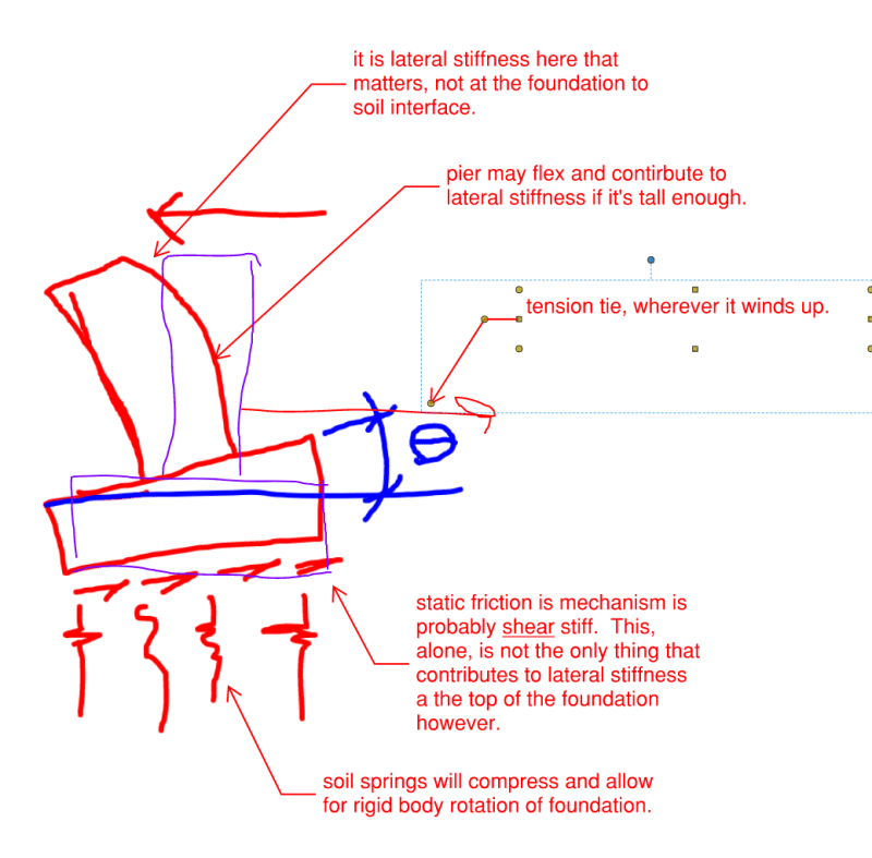
2) In my neck of the woods, the piers would be of a meaningful height due to frost. In such a situation, one needs to also factor in the pier rotation and pier flexibility to properly assess how stiff the foundation would be with respect to the 0.5" tie elongation. OP's much further south, however, so perhaps this is not a concern in his situation. This boils down to the vertical eccentricity between the tie and frame base plates. This is what I assume you alluded to in the statement below although I'm skeptical that 0.9 code check can justify such simplification.

WesternJeb said:
However, too complicated for me and this is why I typically design to a .9 code check so I can make some of those simplifications :).

C01_u286dn.png
 
XR250 said:
the entire slab likely acts as a giant tie and draggy thing that resolves a lot of it.

As the project is currently detailed, the top of the PEMB column pier is at FF, and there is no connection between the slab and the pier. So I don't believe it would be engaged at all in this project, as opposed to the detail WesternJeb posted or in the case of hairpins.
 
Maybe something like this could work for you:

PEMB_ajjonj.jpg
 
utvoler said:
Hit me up in a few months, I'll tell all!

Well if you're on LinkedIn, I've narrowed you down to one of 5 possibilities...only one is in my area...
 
I share bones206's opinion about the dropped tie being a generally good idea if you'll have to drop for the pit anyhow. In the referenced thread, I believe that was a retrofit situation which ruled that out.

OP said:
..but if I'm greatly over-sizing the steel to limit elongation and am well below yield at the design load aren't we still elastic and we would never reach yield elongation? Or I guess that's the point you're making? And to WesternJeb's point it will "shrink" back when the snow melts?

I don't think so. Consider:

1) You need a certain amount of -- not insignificant -- foundation movement to develop passive soil resistance. Whatever it is, it is. For sport, let's call it 1".

2) No matter what size of steel member you use for the tie, its yield elongation will be the same. Large pieces of steel have the same yield elongation as small pieces of steel. For sport, let's use JAE's numbers.

3) 1 + 2 = if you need 1" of foundation movement at the base plates in order to mobilize passive soil resistance, and your steel yield elongation is 7/8" per end, then you have to take your rod 1/4" past yield in order to develop the passive soil resistance.

As WesternJeb and I have been discussing, the matter may be improved if you intend to use static friction but not passive soil resistance. Unfortunately, it sounds as though there may be quite a bit of eccentricity between your base plates and your ties which takes us back to the sketch that I posted previously.


Correction to my sketch: it's the lateral foundation movement at the elevation of the tie that matters for the tie (obviously). It's been a long week debating peer review processes...
 
I concur with KootK on all accounts (unsurprisingly haha). I was envisioning a stubby pier (2' or less) that would be used in my area and is what my argument was based on, thanks for calling that out to think in broader terms.
 
Status
Not open for further replies.

Part and Inventory Search

Sponsor