Continue to Site

Eng-Tips is the largest engineering community on the Internet

Intelligent Work Forums for Engineering Professionals

  • Congratulations GregLocock on being selected by the Eng-Tips community for having the most helpful posts in the forums last week. Way to Go!

PEMB: 240k Kickout Tie-Beam 5

Status
Not open for further replies.

UTvoler

Structural
Oct 7, 2010
49
Hi all! I am working on a PEMB with a 200' clear span, with factored horizontal reactions of 240kip at the baseplate. I am really struggling to get this magnitude of a shear reaction into the the pier and then transferred into the tie-beam. To make things extra fun, I have two frames where my tie-beams will intersect pits in the floor, and so the tie-beams want to drop down 24" below the top of the slab, which makes the pier ACI anchor rod checks impossible without an 8-ft square pier (I also tried the strut-and-tie approach with no luck).

All that aside, my "typical" tie-beam that I am somewhat comfortable with is 24"x16" concrete beam with (12) #10 bars. For various reasons (like welded/mechanical splices, and a slightly questionable approach to lapping the beam bars into the shear cone of the pier) I am thinking of using a concrete encased HP10x42 beam instead of rebar for a tie-beam.

Am I crazy; anyone ever done such a thing? Pro's: I could splice the beam to a setting plate with a heavy bar and hang my hat on the shear transfer; two beam splices in the span is pretty straight-forward; there's not a bunch of rebar to deal with, etc. Only Con that comes to mind is burying a steel beam even though it will be embedded in concrete....not sure why that gives me pause?

Appreciate any thoughts anyone may have!
 
Replies continue below

Recommended for you

Not so fast. I kind of changed my mind.

KootK said:
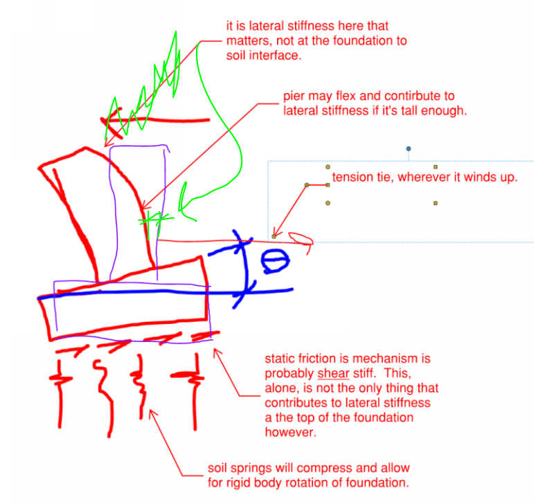
Correction to my sketch: it's the lateral foundation movement at the elevation of the tie that matters for the tie (obviously).

The big elevation difference between the base plate and the tie might make for some pier rotation as I mentioned earlier. I stand by that. However, if the tie and the footing are close in elevation, as I believe them to be, then that rotation will have a pretty minor impact on lateral movement at the level of the tie.

As with most things dirt, I'm willing to do most anything that a geotechnical engineer will sign off on.

c01_c1ua8o.png
 
So counting on passive resistance is out; I should thought a little harder on than before I even posted it.

At Section 5 of the attached, there is a weldment connecting the PEMB base plate to the tie-beam reinforcing which is mid-height of the pier. Max thrust is 167k (D+S), max sliding resistance at the bottom of the footing is 49k. Due to the offset between the thrust load and the ties, there will be overturning to the foundation and/or bending to the tie-beam. I have a hard time with resolving whether or not to count on the sliding resistance to reduce the thrust load that the tie-beam should be designed for in this detail; it seems that the direct connection doesn't care about the sliding resistance. It would seem that as the thrust load increases, elongation occurs in the tie-beam allowing lateral deflection of the pier and rigid body rotation per KootK's sketch while the sliding resistance keeps the footing in place until the load exceeds it. So maybe it starts snowing, and when the thrust reaches 49k there is ~.25" elongation (with the current rebar design) in the tie which allows the pier to deflect and the footing to rotate and as the thrust increases beyond that the footing slides with the additional tie elongation?

Section 8 seems much more straight forward to say by inspection that the thrust can be resisted by the combination of the sliding resistance and the tie-beam.

But I 100% agree with KootK's point that the critical thing is where the top of the pier winds up in all this....seems like an awful lot of discussion for a serviceability issue but I like it!

From a design perspective this is a pretty easy one to KISS-it and ignore the sliding friction for the tie-beam design for sure....really wish I was involved before the contractor bid and won the project!
 
 https://files.engineering.com/getfile.aspx?folder=17a04c7e-0d07-4083-8909-953bb6d26bae&file=S6.01.pdf
Oh, and phamENG why didn't you hit me with that LinkedIn connection? Go Vols!
 
Interesting thread, y'all do have the Butler foundation design manual as a reference yes?

I haven't read all of this yet, however....

KootK - I see that snap through buckling, but I wonder if there's enough stiffness at the knee to resist outward thrust enough to produce it. Can't really check because the knee is the PEMB guy. Plus the column deflects and isn't a good "fixed joint" for the snap-through. The roof diaphragm may offer some bracing along the length, or the erection bracing/cables, but... I suppose it's an engineering judgement question.

If this project is in actually Tennessee, is the snow load right? (I don't do a lot of Tennessee). Are they putting Ct = 1.1 on it for insulation (that's for a ventilated roof, I think, these typically aren't). What about Ce less than one due to exposed/windswept in Exposure B/C?

A roof this large would probably end up with 12 psf roof live load, wouldn't it?

WAIT. The bays are 50 feet apart? That seems way large compared to what I'm used to seeing (pg = 50-60 psf for me though), even so.....

Also, not to edit the PEMB guy, but why is the roof so steep? I'm used to seeing 1/4"/foot on these. The steeper that roof the more thrust you get?

Regards,
Brian
 
lexpatrie said:
Interesting thread, y'all do have the Butler foundation design manual as a reference yes?

Indeed I do. There was a mass sharing of it here a while back thanks to a former Butler engineer. And I've had faxes of parts of it going back to the 90's.

lexpatrie said:
KootK - I see that snap through buckling, but I wonder...

I abandoned snap through once I saw how small JAE's elongation numbers were.

lexpatrie said:
Plus the column deflects and isn't a good "fixed joint" for the snap-through.

I see base plate lateral deflection as adding to snap through potential, not reducing it.

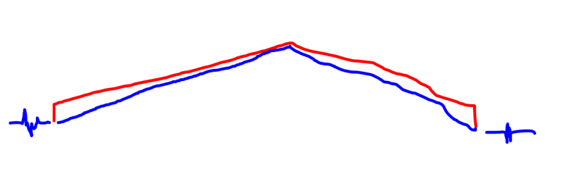
The general premise that I was working under was that, if you make the thing long enough without proportionally increasing the sidewall height, and it approaches the system shown in blue below.

C01_kmpbn5.png
 
And I quote: "As can be seen from Design Example 10.6, a substantial 24 x 24-in column pedestal designed under the provisions of ACI 318-08 Appendix D could barely resist a relatively minor factored shear loading of 6000 lb.....Historically, supplemental reinforcement for tension and shear has not been provided in the foundations used for metal building systems. Implementing the design provisions of ACI 318-08 Appendix D requires a total change in the design and construction practices for metal building systems. The anchor-bolt designs used in pre-engineering buildings for decades will no longer work."

-Sir Alexander Newman, "Foundation and Anchor Design Guide for Metal Building Systems" circa 2013

This is a f@#%%#g impossible project....Anyone want to take over and seal the design as a subconsultant? I think I have about -$25,000 in fee left.
 
utvoler, I haven't read all the recent posts on this so I may be missing something, but if you can't get the load path to work going from base plate to pedestal to tension tie, why not just avoid the pedestal altogether for the thrust force? Set the pedestal lower than the slab, then connect directly to the base of the column with your tension tie. The slab will be poured over the pedestal.
 
Sir?

As far as the pier reinforcement/anchorage breakout question goes, why isn't Newman using the rebar cage in the pier? Some of these anchorage cases don't apply if they are enclosed within stirrups.


Koot - what I was getting at is the stiffness of the support plays a role in the snap through doesn't it? If the knee/knuckle can't offer much stiffness versus the spread? I mean if there's no rigidity at the supports it's a mechanism but the snap-through doesn't happen? Intuitively at least. It's been a while since I handled "classic" stability problems like snap-through.

I still think part of this problem is the size of the bays at 50 feet. That's about 20 feet past normal, it's come up on several threads here as well (2010, ...
Then there's the snow load, Ce snow/wind exposure factor, and the Ct thermal factor all of which are worth some checking. That lateral load is so large it seems like some refinement in the snow loads may help. I thought the PEMB folks had their own chart/design code for snow loads anyway?

Regards,
Brian
 
lexpatrie, OP originally stated the spacing as being 50' but later corrected that to 25'-6". That had me mixed up as well.

I briefly looked at the snow loads on this. I'm not sure what you could realistically do to "refine" (lower) them.
 
utvoler - I thought you were designing a weldment to directly transfer base plate thrust to the tie beam. In that case, anchor bolts would not be required to take any shear from the thrust load. Maybe I misunderstood your intent with the weldment.
 
Eng16080 said:
why not just avoid the pedestal altogether for the thrust force? Set the pedestal lower than the slab, then connect directly to the base of the column with your tension tie
I was engaged on this project after the Contractor's PE did some preliminary design work, and the building was already "bought". Changes to the PEMB at this point "is not possible"...

lexpatrie said:
Sir? As far as the pier reinforcement/anchorage breakout question goes, why isn't Newman using the rebar cage in the pier? Some of these anchorage cases don't apply if they are enclosed within stirrups....That lateral load is so large it seems like some refinement in the snow loads may help
I awarded him with Knighthood for his work in the field....Newman does have commentary and examples for rebar cages. The factored thrust reaction is ~43k, I'm finding that confining this magnitude of shear breakout is basically impossible due to the required bar sizes and geometry restrictions; keeping it within the top 5" of the pier per ACI/Strut and Tie requirements etc. And I checked the reactions with an independent frame model and come up with pretty close results.
 
bones206 said:
I thought you were designing a weldment to directly transfer base plate thrust to the tie beam.
I did that, but wanted a fully reinforced/detailed pier around the weldment but can't get the ties in per Code with my current weldment design; so back to the drawing board maybe. I also have three frames that have one interior column with lower thrust loads of "only" 43k. These three frame have below slab plumbing for bathrooms etc., so was really trying to avoid the tie-beam on these but am having trouble with the pier design.
I need four more weeks of design time and fee, but am two weeks behind and beyond frustrated!
 
If nothing can be done on the PEMB side to reduce the loads, then they are what they are. I know we all want elegant solutions to our poopy problems, but sometimes poopy problems get poopy solutions.

Some possibilities:
- Bypass ACI 318 Anchorage provisions and size & reinforce your piers such that they fall within STM analysis. Pretty sure Koot has good thoughts on this approach.

- Don't use a tie beam, but size the pad under the column to take all the lateral and associated OT moment. Make the pier as deep as possible (parallel to the frame), and possibly have the pier transition to a legit counterfort. Will the footing be monstrous with monstrous rebar? Yes, yes it will.

For your frames with "only" 43 kips of lateral, I'd do a moment footing and not think twice about it.

An aside, if the contractor's PE didn't notice the 240 kips and start to re-evaluate the building choices, then it's time to put on your black hat and set everyone straight about what it's going to take.

Please note that is a "v" (as in Violin) not a "y".
 
utvoler said:
the Contractor's PE did some preliminary design work...
utvoler said:
the building was already "bought"...
utvoler said:
Changes to the PEMB at this point "is not possible"...
Yeah, I get it. Those involved in the project before you made some questionable decisions, and now you get to fall on the sword for them, or at least struggle to make a ridiculous situation work. Sometimes us engineers are too accommodating to this kind of crap.

I still think there must be a solution here though. How about setting a steel tie beam with the top at the slab elevation? The beam sits directly on the pedestal and the column is bolted/welded directly to the top of the beam. At the pedestal location, there would be stiffeners aligned with the column flanges to transfer the vertical load. Beyond the pedestal, the beam would be cast in concrete with shear studs welded to the sides to promote shear transfer between the concrete and beam (giving some additional capacity by engaging the slab). The top of the beam would be exposed since it's at the slab elevation). Done!
 
WinelandV said:
Bypass ACI 318 Anchorage provisions and size & reinforce your piers such that they fall within STM analysis...
-I tried to STM analysis, which was/is a new approach for me so I'm on the struggle bus...I followed the approach in the STM paper based on the petrochemical industry that has been floated around on this sub pretty regularly, but run into issues with steel tie sizes and keeping the ties in the top 5" of the pier as alluded to above. But I feel that STM is the likely only solution I can hang my hat on; I just haven't quite been able to get there yet even with only 43k reaction.
-Counterfort pier and monster footing; I like it but would still have to solve the issue of getting the reaction into the pier.
-The moment footing and pier design for the 43k load is done and I'm comfortable; same challenge getting the reaction into the pier.
"then it's time to put on your black hat and set everyone straight about what it's going to take" - Agreed. Never designed a PEMB with this magnitude of reactions, and so have been finding out just how tough this design is slowly along the way, and I'm in pretty deep at this point...but it's going to take what it's going to take...

Eng16080 said:
Sometimes us engineers are too accommodating to this kind of crap
Guilty as charged, 100%, no doubt.....steel tie beam was an approach considered and discussed way above; I also have two frames where the tie has to go below pits (also discussed and a real PITA).
 
@utvoler - if you absolutely have to have a pedestal that extends above the slab, then concrete is not the answer. Have you thought about using a steel element, see attached.
PEMB2_Idea_qtczkn.jpg
 
utvoler said:
But I feel that STM is the likely only solution I can hang my hat on; I just haven't quite been able to get there yet even with only 43k reaction.

Well... you could use a large hairpin that extends out into the slab to get the development length required for a larger diameter bar. I'm not big on that approach, but it is something people do. I am reluctant to include the slab in the PEMB load path for any reason, but it's an option. One of the concerns is that the slab could be replaced down the road while the building is under load, or the thrust gets applied before the slab is constructed. Just too much faith and hope involved with that detail for my comfort level. Scroll down in this thread to see how the OP's hairpin detail for anchor shear reinforcement thread507-512185.
 
bones206 said:
Well... you could use a large hairpin that extends out into the slab to get the development length required for a larger diameter bar.
I disagree with this, the normal max you can get out of a hairpin is around 10 kips, unless you have more mass and weight (concrete thickness) to provide friction resistance. There is only so much slab you can grab before the adjacent columns influence areas overlap. We don't know the spacing of the columns in this building, but I suspect around 30 to 40'.
 
This wouldn't be for engaging the slab for global stability; the moment-resisting footing would presumably take care of that. This hairpin would solely be for restraining the anchor breakout. So it only needs to be developed on both sides of the breakout plane. The chunk of slab that the hairpin is going into just has to develop the hairpin legs and send the thrust back into the face of the foundation wall in compression. Like I said, not a fan of this detail but it does technically work.
 
Bones206 said:
Well... you could use a large hairpin that extends out into the slab to get the development length required for a larger diameter bar.

ACI 318-14 commentary R17.5.2.9 strongly suggests not using any bars larger than #6 for hairpins.
 
Status
Not open for further replies.

Part and Inventory Search

Sponsor