Continue to Site

Eng-Tips is the largest engineering community on the Internet

Intelligent Work Forums for Engineering Professionals

  • Congratulations SSS148 on being selected by the Eng-Tips community for having the most helpful posts in the forums last week. Way to Go!

PEMB base plate with anchors in the bottom 3rd only 2

Status
Not open for further replies.

canwesteng

Structural
May 12, 2014
1,700
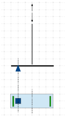
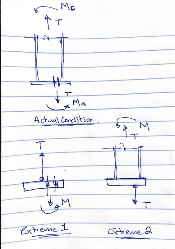
A PEMB vendor has supplied a base plate with anchors only in the bottom 3rd of the base plate - say it was an 18" depp BP, then you have 3"x3" bolt square 6" from one edge. The column is straight and doesn't taper, so surely there is some eccentricity in tension loads here that they aren't reporting? Has anyone else dealt with this?
 
Replies continue below

Recommended for you

canwesteng - there will be eccentricity. It may not be a lot, but it will be there. The tension reaction on the foundation will be at the centroid of the anchor bolt group. The compression reaction will be at or near the centroid of the column. You can only align the center of your foundation with one of these, so pick the one that will give you the easiest and most economical design.
 
I think you can evaluate the effect of the eccentrically placed anchor group. Only you know how the upper structure is connected, thus the load path and intensity.

image_c6fvp3.png
 
canwesteng said:
A lot of speculation going on, and none of particularly germane to the question.
If you give an incomplete picture then people will speculate. Give a broader picture if you want less speculation.

canwesteng said:
I'm wondering about eccentricity caused by uplift on the column.
And what are you wondering about it? Why is this a problem and not a solution? This 'eccentricity' as you call it sounds like a solution to resolve the problem of preventing uplift while still retaining a flexible pinned connection to the footing. During a loading event that causes significant uplift it may in fact it may be LESS eccentric than bolts central to the plate.
You haven't replied to where the bolts are located and they type of building. If they are located on the inward side of a portal frame structure it makes complete sense for the reasons explained already. But unless you elaborate you are just going to have more speculation.
 
Under pure uplift, it seems to me the connection acts more pinned than it would from lateral on the side towards the bolt pattern. You will have some eccentricity because the lifting of the roof beam will cause the column to want to rock with the top towards the bolt pattern side. When would you have pure uplift without some lateral wind if this is a sheeted building?

According to my understanding of PEMB reactions, they are telling you what happens at the bottom of their baseplate. So according to them, there is no moment.
 
canwesteng said:
A lot of speculation going on, and none of particularly germane to the question. I'm wondering about eccentricity caused by uplift on the column.

1) You are correct in assuming that an uplift reaction will be eccentric to the centroid of the column and will thus induce bending in the column.

2) If the column is part of a lateral bent, the moment caused by #1 should be much, much smaller than that caused by frame action. This may be the key to making this check out.
 
How the eccentricty is handled is a function of the stiffness on each side of the joint. I like to think of the extreme situations and work my way to a more realistic answer.

Extreme #1 - replace the column with a cable fastened at the center of the column. It is obvious that the bolt group has to resist the eccentricity.

Extreme #2 - replace the bolt group with a single pin connection. It is obvious that the column has to resist the eccentricity.

unnamed_nrag1g.jpg


My gut feel is that if the column is 18" deep and the anchors are 3" apart you are far closer to extreme #1.

As for the reason of the off-set, I think human909 nailed it 8 posts in.

human909 said:
If the bolt holes are located inward to the building then that would improve the pinned connection behavior under wind and gravitational loads. In fact it makes plenty of sense and seems quite a clever solution.
 
While the PEMB supplier says there is no moment, most all baseplates have some moment present. What you are depicting relates to where the PEMB supplier has "modeled" where the V and H occur on the baseplate. If the location is centered on the bolts, no eccentricity. If not, eccentricity. Well, the PEMB supplier probably has not specified the information in that much detail. We all know the model said it was pinned, therefor, no moment was calculated. For purposes of design, the depth was practically 0 in the model."

To answer your original question, you have eccentricity from vertical loads. You also have some 'unspecified' moment because the baseplate is not truly pinned. Next question, "How much eccentricity and how much unspecified moment?". The the more resistant you make you portion, the more the unknown values will be.

The true fixity of the connection has several parts to it and you do not have control over some of them if you are strictly designing the foundation.
[li]Depth of column (supplier)[/li]
[li]Bolt diameter, pattern and its location inside the profile of the column (supplier) (supplier tends to keep them the same relative to girt line)[/li]
[li]thickness of baseplate (supplier)[/li]
[li]welding of column to plate (supplier)[/li]
[li]foundation dimensions (you) (can make it more resistant to moment) [/li]
[li]bolt embedment (you) (no affect on resistance to moment but has an affect on bolt failure)[/li]
 
I won't raise red flag if the baseplate is furnished with 4 bolts as shown, and two bolts at the opposite end. It is been done quite often. For your case, a review of the calculation is prudent.
 
There is plenty of discussion about eccentricity of uplift. But it still isn't clear that there is much (EDIT or even ANY) eccentricity. Lets consider an efficiently designed pinned columned portal frame that has a span of 25m, has an eave height of 7.5m and a 3degree roof. This is sample portal frame model that comes with the modelling program SpaceGass, so I haven't picked it to prove a point.

Portal_Frame_g63j4t.png

-As you can see there is a 95.33mm deflection (visually exaggerated) at the top of the column at ultimate load in cross winds (This includes dead loads).
-The column used is a 530UB92 (533mm) so the uplift for is now at the 68% mark in the column pretty much precisely where the bolts are.
-Again this wasn't a staged model, I went into this blind to the answer. Feel free to dig out your own designs and run similar checks.

So like I guessed earlier the position of the bolts REDUCES uplift eccentricity and improves the ability for the connection to behave like a pin. Personally I think it is clever engineering and it is something I haven't come across before this thread.


retired13 said:
I won't raise red flag if the baseplate is furnished with 4 bolts as shown, and two bolts at the opposite end. It is been done quite often. For your case, a review of the calculation is prudent.
What purpose would additional bolts at the other end of the column serve? That would make the connection behave more like a rigid connection than a flexible pinned connection.
 
human909,

I couldn't tell if your model is the same as indicated by the OP - a 18" long baseplate for a column, I guess, the same, or close depth, with the bolts centered at 1/3 of the plate length. My two bolts are just to hold the plate squarely in place. I've no way to evaluate the forces on them, as I don't know how the super structure is framed into the column.
 
No it isn't the same 18" long base plate. But that isn't the point. This effect scales linearly. So for similar shaped buildings with similar loads you will get the same results. I could rescale it to an 16" column with an 18" base plate and get the same results but what would be the point?

retired13 said:
My two bolts are just to hold the plate squarely in place. I've no way to evaluate the forces on them, as I don't know how the super structure is framed into the column.
4 bolts at the 1/3 point are more than enough to hold the plate squarely in place. Adding two more bolts at the other end would not assist and world be detrimental to the pinned connection assumption.

While we haven't been given explicit confirmation, I think it is reasonable to assume that the PEMB with a I shape column is a portal frame structure.
 
human909,

The OP is reluctant to provide relevant information... But I think you are probably correct, as the PEMB guys wouldn't do it without acceptable reasons.

 
I need clarification about where the bolts are relative to the girt line of the building. I assumed they were close to the exterior girt line but some of the discussion appears to indicate they are near the inside face of the column rather than the outside face.

Which one is it? The drawing by Canwesteng did not specify which.
 
The bolts are on the outside face. The columns are (supposed to be) modelled as pins by the fabricator, so the uplift shown by human9 shouldn't occur - it should just be uplift on the roof, plus overturning moment. This is born out by the roughly equal compression on the opposite side of the frame. To me, the frame is still stable with the tension resultant at the 1/3 point of the base plate, and the column utilization is mostly going to be governed by snow load cases, and I actually think the eccentricity is beneficial (ie counteracting moment) in the uplift cases. The fact that concrete breakout is a brittle failure mode is a little concerning, but I haven't seen any failures of PEMB buildings and I've always seen them designed like this. It's just more a question of how the PEMB mftr designs the buildings.
 
camwesteng said:
The bolts are on the outside face.
Well than is not the best location for them. My discussion earlier about the advantages of having them on the inside obviously doesn't apply.
 
Former PEMB designer. There's still information missing as to what this column is. There are independent wind columns (don't connect to a rafter/bent above), endwall columns (part of a braced frame on the last frame line) or rigid frame columns (used as a portal). All of those have different behaviors. I can say that it is unlikely any kind of special consideration was made for any moment in the column due to uplift (usually it won't control over heavy gravity loading anyway). Also note, the PEMB designer isn't worried about the anchorage, just the steel capacity of the anchors for the loads imparted by the building. How that gets into the foundation isn't something they are going to worry about.

The anchor bolts are on the outside since the rod bracing, for both sidewalls and endwalls, is usually close to the outside of the building (6" +/- from outside face of column). The bracing is centered on those anchor bolts to eliminate torsion on them from the rod bracing. All the other ones have the same pattern to help limit the number of AB patterns/locations. If you desire them somewhere else, it is likely they can be moved without concern by the manufacturer, as long as it's hasn't already been produced.
 
Anonymous,

Very clear explanation on the location of the AB. However, can you think a reason why for a 18" long plate, only 1/3 of the length is utilized to anchor the column?
 
The PEMB designer probably ran the numbers and only (4) anchors were required. They were placed in the standard location, so 6" from the flange with 3" between bolts. The column is as deep as required for the loads on it to work, and for any framing above to fit.

I'm guessing this column is designed for axial gravity and wind bending as a simply supported beam (I'm thinking it's an endwall column or independent wind column). That's usually the only kind of columns that are that deep at the base, and it's to keep them the same size all the way up for ease of fabrication.
 
Anonymous,

Thanks. That's making sense now.
 
Status
Not open for further replies.

Part and Inventory Search

Sponsor