Continue to Site

Eng-Tips is the largest engineering community on the Internet

Intelligent Work Forums for Engineering Professionals

  • Congratulations cowski on being selected by the Eng-Tips community for having the most helpful posts in the forums last week. Way to Go!

PEMB Wind Post Bracing 2

Status
Not open for further replies.

XR250

Structural
Jan 30, 2013
5,954
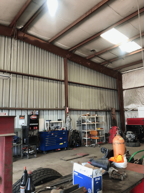
Saw this the other day while getting some tires. The post is about 20 ft. tall and has 20 ft. span girts +/- on each side. Seems like that tiny brace from the bottom of the end frame to the purlin is pretty optimistic for transferring the out-of-plane post load into the diaphragm. Seems the purlin would not be too happy about it either.
IMG_1844_uljmy9.png
 
Replies continue below

Recommended for you

You are right about the lack of purlin bracing, retired13. The only bracing seems to be sag rods, and they don't do much for strong axis bending or compression. Properly designed bridging would likely have prevented the failure.
 
Exactly as thought. The bridging was installed near the top flange that offers no help in this case.
 
Ooh this post still has legs. I'm glad everybody liked my photo. I did search for a close up but I couldn't find one.

Personally I see this as primarily an axial failure of the purlins. And while bridging might have been enough to help they really aren't the problem. The main problem is the lack of a proper compression member from the wind post.

The rod cross bracing really which is normal used to resist the axial forces we are talking about really isn't doing its job as it lacks compression struts.

For what it is worth I designed an extension to this shed which doubled the number of portal bays. My purlin spacing was the same with NO BRIDGING. However my end wall used hollow section members to transfer the wind loads to the walls, again braced with hollow section struts. My portal columns and roof truss were a little larger though. I found the existing members to be a little undersized.

I doubt the building was ever repaired. The owners didn't care. My understanding was the storm that did this way likely a 1:10 or 1:50 year event. I was/am probably the only engineer who looked at this and my contract wasn't to regarding this section of the building. Though I did make my thoughts known.
 
human909,

I agree that a bracing truss is required in the roof plane. But I think you are in Australia, and normally uplift wind loading is the load case that matters. The purlins can experience exactly the type of failure shown in your picture due to uplift. Why no bridging? Bridging is typical in Australian designs, both for erection and permanent reasons.

 
hokie66 said:
human909,

I agree that a bracing truss is required in the roof plane. But I think you are in Australia, and normally uplift wind loading is the load case that matters. The purlins can experience exactly the type of failure shown in your picture due to uplift. Why no bridging? Bridging is typical in Australian designs, both for erection and permanent reasons.

In this case the purlin depth and span and spacing was adequate for uplift without needing bridging. Purlin depth and span and spacing was dictated by the original building spacing.

To be honest though I have skipped on bridging numerous times. Often you might only need to go up slightly in purlin weight to get something adequate and the you skip on installing hundreds of bridging items which is expensive. Labour is where most cost of construction are so saving on labour is where you bring down costs. (Ease and safety of roof sheeting installation also needs to be considered where bridging is not present.)

Larger spans I would often use one row of bridging. But it all depends on what the key design criteria are.

 
Just curious, where are you in Australia, or optionally, what is your wind requirement? And how do you design your purlin systems? I have always used the Lysaght or Stramit tables, and have generally used bridging accordingly. But that is in Queensland, and in generally the higher wind loading areas.
 
This job was in NSW. Likewise I use the Lysaght tables and bridge as required. For continuous lengths over short spans the benefit of bridging is small eg 5%-20%. In contrast for non continuous sections on long spans the benefits of bridging can be very significant 100%+.

For a standard portal frame shed I can imagine that bridging makes sense when designing an economic structural system. However I don't do many of these.** And the one that I posted pictures was an extension so I followed the depth, span and spacing for consistency.

(That said if you continue think my reasoning is flawed feel free to point it out. I welcome feedback, In my current workplace I am surrounded by far too many ignorant engineers! [sad])

**(The last two roofs I designed had ~2,000 tonnes sitting on a superstructure above the roof in an area of 10mx40m) [bugeyed]
 
I am sure you are reading the tables correctly. But I have always used at least one row of bridging per span, for the benefit of the roofers. The insulation which you queried in a post above is typical here, and the bridging makes for a much more stable environment for the roofers who have to spread the insulation just before installing the roofing.
 
In the second photo, provided by human909, it looks to me that the purlins failed by lateral torsional buckling in bending (probably due to uplift) and made worse by limited purlin bracing, i.e. sag rods not nearly full height bridging.

What is the bay spacing shown? (Looks like ~30 ft / ~10 m)

The axial load in the brace strut purlins will increase going down the roof from the ridge to the eave. Note the purlin buckling is relatively similar all down the roof until near the eaves, not concentrated in the strut purlins at the X-rods where the brace sections are located/adjacent in the open web roof beams.

Jim H.

27 years designing and building/selling Butler Buildings.
 
Jim,

What are your thoughts on the my original picture?
 
jimstructures said:
In the second photo, provided by human909, it looks to me that the purlins failed by lateral torsional buckling in bending (probably due to uplift) and made worse by limited purlin bracing, i.e. sag rods not nearly full height bridging.
I'm curious on why you would conclude that when the purlins were more than sufficient to withstand uplift without bridging.

When we are talking about combined actions 3 easily identifiable loads it is somewhat moot to say that it was A or B or C which caused the failure. That said I'm surprise with the insistence on LTB here. There are four main reasons why:
1. LTB is generally failure normally involves the whole member.
2. The rod bridging and the roof sheeting very likely provide enough twist restraint to prevent LTB for the spans here. (6m)
3. Like I've said before the axial loads were quite high. The wind was coming from the right. There was no load path for the half wind loads on the wall except for through the purlins/roof. Again the wind posts were simply supported and rotation was evident in the foundation.
4. This was the only bay affected. The only bay that had purlins being compressed under axial load.

Like I said early the if you consider the roof/purlin as a monolitic member then it is a very slender member under combined axial and bending stress. The bottoms flanges yielded in compression.

jimstructures said:
The axial load in the brace strut purlins will increase going down the roof from the ridge to the eave. Note the purlin buckling is relatively similar all down the roof until near the eaves, not concentrated in the strut purlins at the X-rods where the brace sections are located/adjacent in the open web roof beams.
The axial loads in the purlins would be at their peaks on the purlins closest to the wind posts. They the axial load would be the highest towards the centre of the roof.
 
In the case of uplift, the bottom flange is in compression, that may leads to instability and prone to buckling. However. For this case, we don't know which mode of failure occurred first, yielding or buckling. But the purlin obviously was not sized adequately.
 
I feel like I'm flogging a dead horse here but...

retired13 said:
But the purlin obviously was not sized adequately.
I would dispute this. Uplift is only 30% of the story.

The purlin was sized perfectly adequately for the expected loads exerted on the roof as per the typical design approach to purlins.

What was not adequate was the load path of wind forces on the wall (to the right in the photo). 50% of the wind load on the 24mx10m face had nowhere to go but through the purlins. Whilst it is not unknown, it is certainly a long way from standard practice to expect the purlins to take significant axial loads. Normally you would have some sort of plan bracing in the roof for this role. This building lacked this load path.

(Also A quick back of the envelope calculation reveals that the axial load stress is expected to be more than 50% higher than the flange stress from bending.)
 
XR250,

I would like to see a complete picture of the endwall (?) frame to determine if it is a pinned/braced frame or a rigid endwall frame. Is it a half load frame or a full load width/expandable endwall frame? Most of the endwall windload (based on trib. width) is going into the roof beam at top of the endwall post shown in the picture and then mostly transferred into the roof purlin over that post.

The tiny fly brace/flange brace (you mentioned) serves to provide bracing to the bottom flange of the roof beam in the compression areas of the roof beam and not to transfer endwall windload to the roof structurals (purlins). Most of the endwall wind load is transferred to the roof stucturals by the purlins bolted to the top flange of the roof beam. There are normally a variety of connections available to transfer the wind load from the roof beam to the purlins.

Most metal building manufacturers assume that the paneling is not capable of acting as a full fledged diaphragm to transfer diaphragm type loads from the Main Wind Force Resisting Systems, i.e. frames to the foundation. A rod bracing system must be supplied to accomplish that transfer. The number of fasteners would have to be increased (doubled) to accomplish a diaphragm system and it would only apply to screw down panels not standing seam or insulated metal panels.

The endwall columns only appear to braced on the outside flange not the inside flange, though it is hard to tell from the picture.

Jim H
 
jimstructures said:
Most of the endwall windload (based on trib. width) is going into the roof beam at top of the endwall post shown in the picture and then mostly transferred into the roof purlin over that post.

So, that is the impetus for my original post. How is the out-of-plane load from the top of the column getting into to purlins without rolling the beam over?
 
XR250 said:
So, that is the impetus for my original post. How is the out-of-plane load from the top of the column getting into to purlins without rolling the beam over?

So for my contribution in derailing the thread from the original post. The out of plane loads are getting into the purlins as you originally surmised, mostly if not completely by the fly brace. The triangulation between the wind post, the brace and the top/bottom flanges of the beam complete a stiff connection albeit putting an additional bending load on the purlin.

If the purlin can handle this additional bending, uplift and the axial from the wind post then you are all well and good. But you are asking a bit much of a purlin that is normally only for roof loads. The result of asking too much is shown in my photo.

If your purlins in that photo are thin cold rolled member I'd be worried. If they are thicker flanged hotrolled channels then I see it as a capable system. I can't tell from your photo if their thickness.
 
If you properly slot the connection from the beam to the wind post, the wind force goes entirely into the diagonal (which induces an additional compression component in the post.

Of course, the compression component in the diagonal needs to be resisted by the purlin, and the purlin forces are exacerbated by the fact that you will have significant uplift on the purlin at the same time you have windward force on the wall.

Some other things to look out for (or just ignore is it suits you): the beam is flexible and the slots tend to bottom out, and purlin gravity loads put a force in the diagonal - how does that force get resolved?

Some PEMBs have separate compression struts in addition to the rod x-braces so that the purlins don't do as much work in compression.
 
jimstructures said:
The tiny fly brace/flange brace (you mentioned) serves to provide bracing to the bottom flange of the roof beam in the compression areas of the roof beam and not to transfer endwall windload to the roof structurals (purlins). Most of the endwall wind load is transferred to the roof stucturals by the purlins bolted to the top flange of the roof beam. There are normally a variety of connections available to transfer the wind load from the roof beam to the purlins.

human909 said:
So for my contribution in derailing the thread from the original post. The out of plane loads are getting into the purlins as you originally surmised, mostly if not completely by the fly brace. The triangulation between the wind post, the brace and the top/bottom flanges of the beam complete a stiff connection albeit putting an additional bending load on the purlin.

Ok, now I am confused....
 
I probably won't clear up the confusion by this comment.... What jimstructures says is how the system is likely designed to work.

jimstructures said:
The tiny fly brace/flange brace (you mentioned) serves to provide bracing to the bottom flange of the roof beam in the compression areas of the roof beam and not to transfer endwall windload to the roof structurals (purlins). Most of the endwall wind load is transferred to the roof stucturals by the purlins bolted to the top flange of the roof beam.

The problem is that for this load path to work then the torsional stiffness of the roof beam needs to be significantly greater than the torsional stiffness provided by the fly brace. (which it almost certainly isn't)

Thus the fly brace would become part of the load path of the end wall wind load whether it was designed that way or not.
 
Status
Not open for further replies.

Part and Inventory Search

Sponsor