Continue to Site

Eng-Tips is the largest engineering community on the Internet

Intelligent Work Forums for Engineering Professionals

  • Congratulations cowski on being selected by the Eng-Tips community for having the most helpful posts in the forums last week. Way to Go!

PEMB Wind Post Bracing 2

Status
Not open for further replies.

XR250

Structural
Jan 30, 2013
5,954
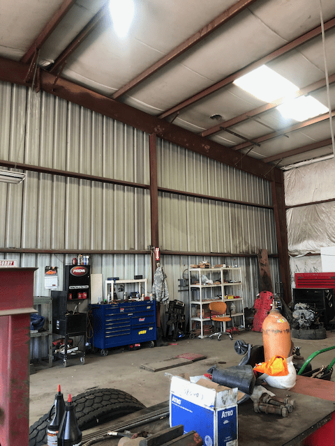
Saw this the other day while getting some tires. The post is about 20 ft. tall and has 20 ft. span girts +/- on each side. Seems like that tiny brace from the bottom of the end frame to the purlin is pretty optimistic for transferring the out-of-plane post load into the diaphragm. Seems the purlin would not be too happy about it either.
IMG_1844_uljmy9.png
 
Replies continue below

Recommended for you

Diaphragm? What diaphragm? It's probably better to think of the wind posts and girts as a sort of steel "net" to catch the wind...
 
Remember that this is a PEMB ... Probably Engineered but with Minimum Bracing.

Mike McCann, PE, SE (WA, HI)


From what I've seen of PEMB design those braces are to laterally brace the bottom flange of the frame.
And phamENG is correct. The roofs are so tiny that they're not used as diaphragms.
Here's a picture of a PEMB vs. Hurricane Michael.
 
 https://files.engineering.com/getfile.aspx?folder=d19bb30d-aa3c-4133-8d3e-b7d140bda5de&file=IMG_2556.jpg
I think the sheet metal deck's contribution to diaphragm should not be overlooked. At least, its effectiveness should be evaluated before write it off. Here is an article from the Structural Magazine, Link, and below is a quote from the manufacture.

Cannam said:
Steel Deck Diaphragm
The steel deck sheets used for roofs and floors provide support for gravity loads between the joists and/or beams. Once installed, these sheets can also be used as a horizontal brace, therefore, allowing the steel deck to act as a diaphragm.
 
retired13 said:
I think the sheet metal deck's contribution to diaphragm should not be overlooked. At least, its effectiveness should be evaluated before write it off. Here is an article from the Structural Magazine, Link, and below is a quote from the manufacture.
I agree with alot of caveats. I was going to comment earlier but there are sufficient unknowns for me that I didn't want to look silly. (I didn't even know what I wind post was until I looked it up. A terminology difference.)

The 'bracing' is LTB fly bracing for the portal frame, I wouldn't consider it part of the 'wind' bracing as such but it would be a part of the load part due to the way the wind posts attach to the portal frame. Also that roof looks like it is sagging and it has been confusing me. Is that insulation under a sheet metal roof? Or an optical illusion?


Getting back to the sheet metal roof diaphragm it definitely can work. But it needs to be done correctly and without further information on this building I would suggest it does look dicey. I've seen the end bay of a large industrial portal frame fail because it lacked compression struts. It had rod cross bracing in the roof so it looked like somebody tried, but there was nothing but the cold rolled purlins and roof to take the compression forces. They buckled, the entire frame moved inwards, foundations crack and the large roller door blew in, possibly saving the wall from further damage.
 
retired - on a lot of the big PEMBs or the newer custom PEMBs they do use steel deck as a competent diaphragm. And even if the "deck" on a typical shoebox PEMB can act as a diaphragm, look closely at the load path. Consider the light gauge Z-purlins sitting on top of the rigid frame. There's rarely any bracing for those to prevent rollover, so your "diaphragm" can only transfer what 8" tall x 16 gauge thick pieces of steel sheet can do at 3' on center. It's not much. Most of the typical PEMBs rely on discreet bracing in the roof. Not all, but most.
 
human909,

Yes, that is insulation under the roofing. Quite typical.

That looks like a building of substantial size, and I would never consider using the roofing as a diaphragm. Roofing is for shedding water, not for bracing. If the sheets are fixed through their crowns as is appropriate for water shedding, or if it is a standing seam roof with sliding clips, all the more reason not to consider the roofing as a diaphragm.
 
human909 said:
Getting back to the sheet metal roof diaphragm it definitely can work. But it needs to be done correctly

This is the message I wanted to convey. There is proven method, but need to carefully do it right/correctly. My comment is generic in nature, not to specific case, nor the one in this thread.

SDI Diaphragm Design Manual (2nd Ed) is attached for interested readers. Link
 
Yes I think we are mostly in furious agreement here.

This is the building i mentioned earlier. You can see the line where the purlins buckled and folded. You could also see cracks significant cracking in the foundation around the wind posts. The entire wall moved inwards.
IMG_20140819_113846_cpww1e.jpg


Portal was pretty big something like 24m wide and 12m high from memory. Nothing stopping inwards movement except for the compression strength of the purlins and sheeting.
 
Nice photo. Compare the purlin in the OP's photo, the stiffness seems differ, visually speaking.
 
When I was a junior I did a good few of these buildings to British Standards.

Looks like a portal frame structure with a gable wind post, typically the wind posts have vertical slots at the top to prevent transfer of vertical load into them. The restraints from the purlins typically restrain the bottom flange of the roof beam for when it goes into compression, typically due to wind loads. As you stated the wind post will likely transfer a lateral force to the bottom flange of the roof rafter, but i doubt this force will be much. For love nor money I cant remember how or if we even dealt with this force, given the size of force relative to the size of beam and thats its restraint along the length of the bottom flange, however the direct load path is likely as you stated into the brace and into the roof. If i did some quick and dirty maths using 1kPa wind and a wind area of say 12m2 (20'x6.7') with factor of safety of 1.4 then your talking about 17kN (3,400lbs) in a diagonal brace thats 17*1.41 = 24kN. Most angle sizes should be able to take this compression force. The purlins are already designed for a uniform UDL, the greater of snow or a live load (typically 1kPa). It's plausible the point load in the opposite direction (upwards) close to the purlin support will not create a larger bending moment that the vertical downwards UDL force.


steveh49 said:
Human909, did the purlins buckle about their strong axis?
The purlins were bent about their strong axis. However the composite purlin/sheeting member bent about its weak axis. Wind was coming from the right in the photo. So the members were likely experience significant compression as well as bending from uplift and the fly brace. More specifically I would suggest the bottom flanges of the purlins yielded under combined axial and bending compression.

I expect the damage would have been more significant had the roller door not blow off its tracks.
 
Does presence of the rod braces have any significance in this whole episode?
 
retired13 said:
Does presence of the rod braces have any significance in this whole episode?
The rod braces would be effective if combines with compression struts between first two bays. I don't see much benefit to them without a competent compression member.
 
Thanks for the pic, human909. That is the mode of failure I was envisioning for this building if it ever met a hurricane. Seems like a tough job for those purlins to resist wind uplift and the bending due to the strut without a whole lot of LTB restraint.
 
XR250 looks like you have a valid concern, wish i could take back my comments now :(

Looking closer i dont see any ridge or eaves beam, which is alien to me. I also had a look at an old job just to re-educate myself. Back home typically their is usually comp/tension memebers to transfer wind back to the roof bracing system (see attachment), or i assume bracing system can be at the end bay. As for a diaphragm roof i have no experience. Also construction techniques between BS and AISC/CSA may differ.
 
 https://files.engineering.com/getfile.aspx?folder=cf591d44-2103-4b70-8ea3-6320f4f299ab&file=20200613_112040.jpg
In my opinion, the failure was caused by strong axis bending (wind uplift) and compression (lateral wind), and the purlin was not adequately sized per unbraced length of the bottom flange.
 
Status
Not open for further replies.

Part and Inventory Search

Sponsor