Continue to Site

Eng-Tips is the largest engineering community on the Internet

Intelligent Work Forums for Engineering Professionals

  • Congratulations KootK on being selected by the Eng-Tips community for having the most helpful posts in the forums last week. Way to Go!

PEMB with full basement

Status
Not open for further replies.

Ben29

Structural
Aug 7, 2014
316
I am designing the foundations for a PEMB. The building will have a full basement and the PEMB columns will sit on pedestals. The column baseplate will be elevated to the first floor elevation. I am also designing the first floor framing. The architect originally wanted steel bar joist (non composite) floor system with a 4" thick concrete deck. But I am starting to convince myself that composite beams are the way to go.

I am trying to figure out how to brace the PEMB column base against the horizontal thrust. My thought is to have beams frame into the column pedestals via a steel plate bolted to the pedestal via epoxy anchors or CIP anchors. Is this a bad idea? Is there a better way?
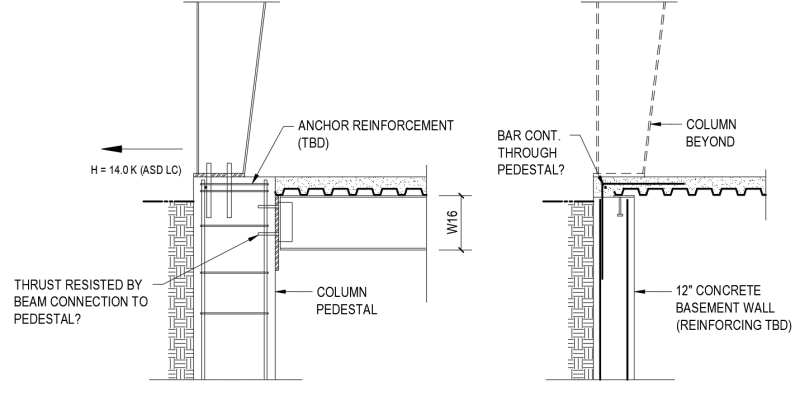
Screenshot_2023-06-09_150043_rku2t5.png
 
Replies continue below

Recommended for you

You could rely on the beam to wall connection to resist the thrust. 14k is not a huge load and could be resisted by the epoxy anchors in tension. Or, why not just rely on the soil to resist the load?
 
This is a new one for me, I would have pushed hard to do a standard building and stay away from PEMB. If I had to do this though, I would use rebar hooked around the anchors, extend the rebar out and weld them to the steel beams and use the steel beams as the tie beam. Another possibility is tie beam rebar in the 4" concrete over steel deck, if you can get proper cover?

@Motorcity - To use the soil passive pressure you would theoretically need to engage the soil, which beams some outward thrust, if you designed the beam details to accommodate this movement without restraining the wall then I could see this happening. The issue there though is concrete breakout with small edge distances in the concrete.
 
I might try to bear the beams on top of the concrete columns, and bolt the steel column base plates to the top flange of the beams.


Your approach is reasonable..

But ,I would prefer hair -pin reinf .at pedestals at the mid. deck level and field bend of exterior wall reinf. fixed in the deck slab..


I cannot give you the formula for success, but I can give you the formula for failure..It is: Try to please everybody.

 
I've seen this, but it always worries me. The whole PEMB analysis is based on the support being pinned, but laterally rigid. If you introduce a spring there:
[ol 1]
[li]Can the PEMB design take it into account?[/li]
[li]How do you define that stiffness and convey it to the PEMB designer?[/li]
[li]And even if the supplier can, will they? My experience is that you get one bite at the analysis apple. [/li]
[/ol]
 
As to my suggestion above, I don’t know why you would depend on two steel to concrete connections for the thrust when one steel to steel connection works. Direct force transfer is always better than indirect.
 
hokie66 said:
I might try to bear the beams on top of the concrete columns, and bolt the steel column base plates to the top flange of the beams.
I like the idea, however I'm not sure the PEMB supplier would go for this as they don't like to change how they do things, which includes having their columns flush mount on top of the concrete. The issue I see with this is that if you had the top of beam flush to the bottom of PEMB column, then you would either need to have an elevated concrete on steel deck above the beams, therefore you need to consider the edge attachments at wall between the columns, or you would need to use angles hanging from the beams and single span deck between beams, which would cause cracking/joints everywhere.
 
I am with HTURKAK depending on the unbraced length and loads (type and magnitude) supporting the PEMB with a cantilever reinforced concrete column is reasonable. You need to consider the deflection compatibility at the connection and design the RC column for the loading. Based on the finishes involved you may considering putting a expansion joint between the exterior wall and the first floor.
 
One thought on the epoxy anchors: they could potentially be in sustained tension to varying degrees for the life of the building. Not sure I would be comfortable with that. Would prefer to see a more direct/reliable tension connection.

I’ve designed PEMB foundations where the frames sit on elevated walls/piers. It’s really structurally inefficient but it seems to come up a lot in maintenance type buildings. Kind of the same situation as OP except without the benefit of backfill to the top of wall. I’ve been able to make these work as cantilevered moment resisting foundations at similar lateral thrust loads. So to simplify and “future proof” OP’s foundation, I’d try to design it as if the backfill and slab didn’t exist and just make the footings large enough to take the overturning moment. The beam and slab connections would then be detailed so they don’t take tension. At higher lateral loads this approach would probably become unfeasible, but at 14 kips I think it could be made to work.
 
Bones,
I was thinking of doing that too. Quick and dirty calcs on my moment foundation was coming out to be 11ft x 11ft square footing.
 
Sounds like the right ballpark. But to Jed’s point, this will inherently introduce some support flexibility that could affect the stresses in the frame. It’s a judgement call… I have only done this type of thing with relatively small thrust forces where I felt the foundation tilt would be negligible. If it’s a significant span I wouldn’t be comfortable without a direct tension tie.

 
Sorry to belabor my point, but a direct tension tie is freely available...the floor beam. Anything else is just simple detailing. If the PEMB supplier can't furnish the columns so that they sit at the bottom of the slab rather than the top, they are not a company worth working with.
 
Well PEMB's have the benefit of not needing your business to be blunt. And at the end of the day who looks worse the EOR for detailing something that no one bids or a PEMB for refusing to bid a job. Its best to go with industry standard unless there is money involved and a job that is spec'ing PEMB is not a job with money to burn.
 
I think I’m a little biased because unfortunately I have to modify PEMB’s often. Never have drawings available or know what the original foundation scheme was. So my mind went to someone modifying OP’s building years later may not realize that the beam or slab is a tension member.

I admit it’s an unlikely scenario, but I heard a building around here collapsed when they replaced the slab, not knowing it had hairpins taking the thrust.

Not sure the tension tie detailing would necessarily be simple. May also introduce erection sequencing constraints, additional inspections, field welding etc. In the end it might be cheaper to pour an extra couple yards of concrete per footing. But I agree if there’s a tension tie, a more direct and reliable load transfer from column to tie is desirable.
 
My above perspective is from experience. Story is the owner thought they were a big shot since they were ordering 2 buildings total 15,000 sf (not even a large order for PEMB). They tried to push the PEMBs to make a bunch of special design changes and this approach was counter to the general contractor's and structural consultant's (SEOR) advice. They wanted the owner to be realistic about the situation. Eventually communication broke down during separate negotiations with two major nation PEMB supplier. No one wanted to touch the job and the change orders were rolling. Finally after 9 months the owner had to fork over a change order to get the project moving and hire another structural consultant to do a delegated design for a stick built metal building.
 
PEMB guy here.

I agree with hokie66. PEMB companies base their baseplates elevation "from finished floor." In this case that would presumably be the top of the first floor slab. They can provide their baseplates at that elevation, above it for grout, or below it whatever distance to recess the baseplates. All 3 are extremely common.

Just make sure that however your process is, you communicate that the baseplates are (for example) 14" below finished floor. Show the beams that are not by the PEMB supplier and their field welded connection. Be sure to call out that the beams and their connections are not by the PEMB and that they don't contribute any meaningful forces to the PEMB columns. That will avoid scaring anyone off from bidding the job.

The beams will, of course, transfer some vertical force to the bottom of the PEMB columns. However, with effectively zero buckling length, and considering that the PEMB columns will have their sizes controlled by bending and there is zero bending at the column base, you can safely add whatever vertical load to the PEMB column without it having any impact on their design.

Another thing I see fairly regularly are buildings where the EOR has designed extra stories within a PEMB. When they do that, they report their reactions and the PEMB designer adds those loads to their rigid frames. That approach would also work and would perhaps be the more professional way to handle this connection but either way, it will add zero cost to the PEMB.
 
Do some of you think that your meek acceptance of the dictates of PEMB manufacturers is damaging to the profession? What is wrong with real engineered buildings, as done in most of the rest of the world?

Sandwich Engine, thanks for your input. Good to hear that PEMB manufacturers are not as intractable as some here think. It is probably because they don't bother to try to communicate.

One correction to your post. The beams would not transmit vertical force to the PEMB columns. The columns would sit on the beams, and would be probably bolted, but possibly welded, to the beams.
 
I agree with you that "real engineered building" is better just pointing out that you get what you pay for. No one is going to Home Depot to buy a shed then demanding to see calcs on the ridge beam. Some how there is a metaphor there.
 
Hokie66,

I'd weld it to the PEMB column. You could call out a bolted connection but that would require coordination between the PEMB detailers and the steel detailers. I've seen that done but more often than not, the construction guys request to weld it anyway because something doesn't line up.
 
Status
Not open for further replies.

Part and Inventory Search

Sponsor