Continue to Site

Eng-Tips is the largest engineering community on the Internet

Intelligent Work Forums for Engineering Professionals

  • Congratulations KootK on being selected by the Eng-Tips community for having the most helpful posts in the forums last week. Way to Go!

Perimeter grade beam and helical piles for a manufactured home 1

Status
Not open for further replies.

sebas-1024

Structural
Oct 7, 2020
14
Hi,

I'm currently responsible for the design of a manufactured home foundation, the client wants to have it supported by a perimeter grade beam which at the same time is supported by piles. I'm having a hard time coming up with a way to confidently analyze the foundation system due to several factors (bear with me as I'm not experienced at all when it comes to manufactured homes supported by grade beams on top of helical piles):

1. The home is comprised of basically 4 shear walls that transmit all of the loads to the foundation system, this means that wind and seismic loads act in an orthogonal direction to the grade beams, this induces torsion on the grade beams and I can't seem to find anything on torsion analysis for grade beams. On the other hand, I was thinking that an acceptable approach could be to have each beam resist the vertical loading of the shear wall on top of it but resist the lateral loads of the shear walls that are perpendicular to it, this would lead me to ignoring any torsional effects and go about a simpler design for it. I'm not positive on the latter though, is that a logical assumption at all to make in this case? (see attached sketch).

2. The idea of having a perimeter grade beam is to eliminate any lateral loading and moments from acting on top of the piles, the initial idea was to brace the piles with a cross bracing system but the client decided against it as they feel that it won't pass local jurisdiction (California doesn't seem to like non-concrete foundations). I'm assuming that, similar to isolated footings, a grade beam can be expected to absorb these loads without transmitting them to the piles, therefore having the piles only resist the vertical loading. Is this approach a correct interpretation of the load path for this foundation system? Or will the piles still receive any moments an lateral loads that go through the grade beams?

3. The connection bracket for the pile needs to be designed obviously, but the documents that I currently have regarding our manufacturer don't go over that part of the design, they only show a few tabulated capacities that may or may not work for me depending on what's determined above regarding the lateral loading. What I mean is that the lateral capacity according to these tables is below the required strength for lateral loading IF the piles are considered to be receiving these loads(we're looking at 1.27 kips of capacity vs a 2 kips load for the most loaded piles). Who determines which is the correct way of designing such a connection (any standards or publications regarding this)?

I know I'm asking a lot of questions but I want to provide the client with a proper design that can pass local jurisdiction without any problems so I'd appreciate any assistance or comments regarding this. Thanks a lot.
 
 https://files.engineering.com/getfile.aspx?folder=e2fc1a4a-4082-49c4-8ab3-2d2f4a83bed9&file=IMG_20210219_045129.jpg
Replies continue below

Recommended for you

We use this setup a lot in my local jurisdiction (Alberta). I'm also using it this month for a project in the Grand Teton area of Wyoming which, to my surprise, is pretty high seismic. So you and I are rowing the same boat here.

OP said:
I'm not positive on the latter though, is that a logical assumption at all to make in this case? (see attached sketch).

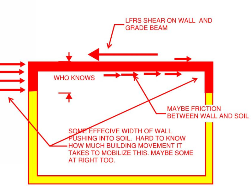
The usual load path story that we tell is that the grade beams resist only the LFRS shear forces oriented coincident with their longitudinal axes. And the vertical, shear wall chord forces of course. So no torsion on the grade beams. And that's a good considering how difficult it would be to detail your grade beam connections at the supports to resist any accumulated torsion.

OP said:
Is this approach a correct interpretation of the load path for this foundation system? Or will the piles still receive any moments an lateral loads that go through the grade beams?

I normally specify LFRS lateral loads acting on the tips of the piles which, unless they protrude out of the ground significantly, will not be cross braced. The sketch shows another load path story that I've seen told on many occasions. It's a bit dubious in my opinion owing to all of the unknowns and the need to shift the building a fair bit before the soil resistance is mobilize.

OP said:
Who determines which is the correct way of designing such a connection (any standards or publications regarding this)?

You and I do usually. If you post a proposed detail, meaningfully complete, I'd be happy to critique it for you. Some general considerations:

1) Bearing stresses where the grade beam rests on the pile head.

2) Hold down capability of the pile to grade beam connection. Usually headed studs, sometimes deformed bar anchors.

3) Consideration of effective shear capacity at joint if your grade beam will be significantly wider than your pile heads.

4) Consideration of effective shear capacity at joint if your pile heads will project above your grade beam bottom steel.

C01_cummkq.jpg
 
Thanks for your replies guys,

Kootk, following up on your response, other questions have come up on my end an I wanted to try and get an answer from you since you seem to be experienced with this foundation design.

1. I was investigating on the actual design of the grade beam, and it seems people recommend that they're designed as normal load bearing beams due to the fact that there's a wall standing on top of it so it does bear a load. The thing is, I tried that and I feel like my design is too demanding. I proposed a 25"x25" section and modeled it on STAAD.Pro along with the piles as fixed supports. But it results in the design asking for a 4.32 sq. in. steel area which to me seems excessive and obviously costly. Adding the beam to the model also resulted in much higher horizontal reactions, I'm unsure as to what is causing it, specially given that I'm not performing any seismic analysis, just applying the static reactions that were given to me by the manufacturers.

2. Regarding the embedded bracket, I get that I'm supposed to design it but according to what design methods? I've never even heard of this sort of design, the pile manufacturer that I'm supposed to perform the design for only has the strength for 2 of the smaller piles and those are unable to withstand the loads (and that was even before I got his horizontal load increase after adding the grade beams).

I know I'm asking for a lot but there's no one I can really turn to for this design and I'm a pretty lost (as you can obviously see).

Thanks in advance.
 
What's your pile spacing? That beam size seems excessive, the reinforcing less so but still high. Generally speaking helical piles would be considered a pinned support. They have negligible moment capacity. That may improve things slightly.

I would expect to have something like a 10"x24" gradebeam with somewhere between 1.9 and 3.1 in^2.
 
The piles are spaced at 5'-2" at the most, to be honest I sized the beam like that because I'm not sure on how to proceed with the bracket design (basically that it fits and doesn't surpass the concrete breakout capacity). Regarding the type of support, wouldn't it be fixed considering the fact that I'm embedding the pile into the grade beam? And then it's a matter of going through LPile or something similar to determine the lateral capacity of the pile. However, the idea of using a grade beam in the first place was to somehow reduce lateral demand on the piles, seems like it's having a completely opposite effect for some reason though.
 
Where I practice the helical piles are of such a narrow diameter that their lateral capacity is minimal, mainly due to the bearing area of the soil on the shaft being so small. And you have piles at 5'-2" and still need that much reinforcing steel? Something has to be wrong somewhere, do you have a plan view also showing the framing direction of the pre-manufactured home.

Also where I practice, the helical piles are cut off at the appropriate elevation after the fact and a plate with nelson studs is welded on top. In the grand scheme, because the beam is so stiff and the helical shafts aren't, you should be getting minimal moment transfer from beam to pile.

I know I said 10" above for a beam width, and that is where I'd be comfortable going to give the helical pile guy some installation tolerance. But there are some guys in this area that would put that home on a 8"x24" gradebeam with pile spacings closer to 8 ft.

Assuming a reasonable tributary width of 10 feet (I don't even think you're buying a 20 ft wide manufactured home without it being split in half) you really shouldn't have much more than 1400 lbs per ft assuming maximum 40 psf snow, and standard timber roof, wall and floor construction.
 
A few thoughts:
1. Grade beam depth is based on plumbing req'ts. One needs to be able to crawl under the unit to make the final connections. 2'-0" above grade is a common minimum, but that is not great if you are the plumber or the hatch is miles away from the connection.
2. You need to know what you have for local piles. We work in an oil patch area, and the minimum diameter we use is typically 4"d. There are many supplying small square shaft piles with a helix on the end, and that will make this much more challenging.
3. Your 25" grade beam width is excessive. I agree with jayrod that 10" is more practical. 8" is also common since the residential contractors are usually exceedingly frugal.
4. Our common connection is a simple rectangular plate field welded to the pile after final cut off. That plate comes with a number of rebar welded to it that are embedded in the middle of the grade beam. I am not a fan of HCA's for this application. On larger diameter piles we have cut out part of the center of the plate and filled the pile with concrete.
5. Expect a number of piles to be off center in one or both the x and y directions. Residential contractors are the worst, and screw piles wander during the install in many cases.
6. A grade beam is a good solution. This is a very cost conscious industry and many use plastic skirting. If your soils are prone to any heaving, plastic skirting tends to heave and buckle at some point since the building is fixed, and the subgrade is not.
7. You will need to discuss the final grade with the owner. It could be they want to bury some part of the grade beam. Obviously soil embedment will play a role in your lateral load question.
8. Make sure you either require engineered piles or logs to prove the installation specs were met. Every contractor that owns a bobcat seems to think they can install screw piles these days and the understanding of screw piles by many of them is horrible. The number that have any sort of method to record the final installation specs is surprisingly low.
 
Status
Not open for further replies.

Part and Inventory Search

Sponsor