Continue to Site

Eng-Tips is the largest engineering community on the Internet

Intelligent Work Forums for Engineering Professionals

  • Congratulations SSS148 on being selected by the Eng-Tips community for having the most helpful posts in the forums last week. Way to Go!

Perp vs. TP - mini quiz - ISO 1

Status
Not open for further replies.

cr7

Automotive
Dec 21, 2019
65
Hi,

me and my coworker (both senior metrologist on the paper) are trying to decode this. And at least I can speak for myself, I don't deserve anything more than junior for not knowing this at 3 o'clock in the morning.

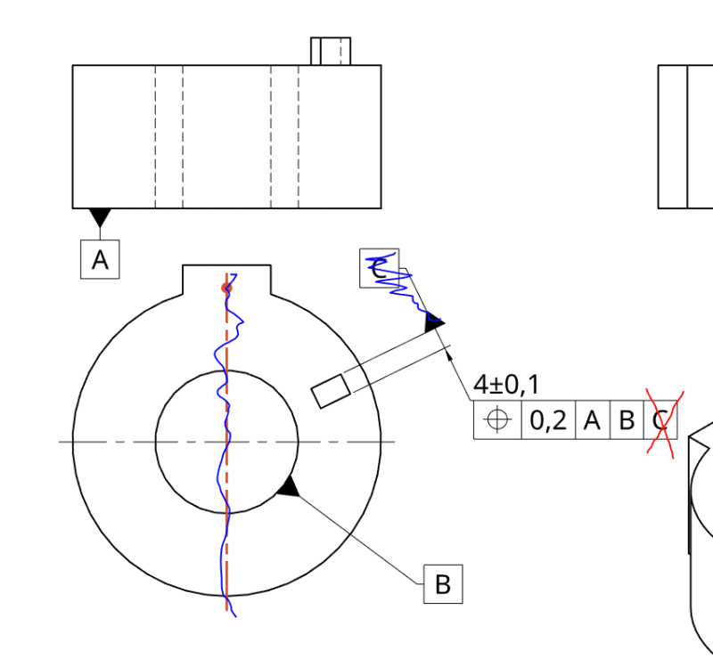
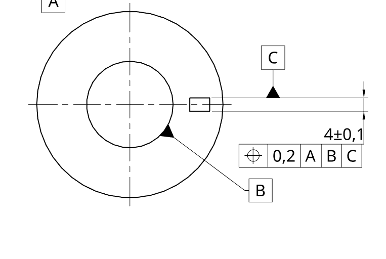
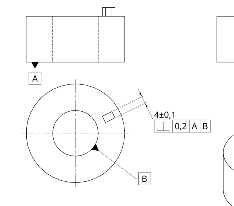
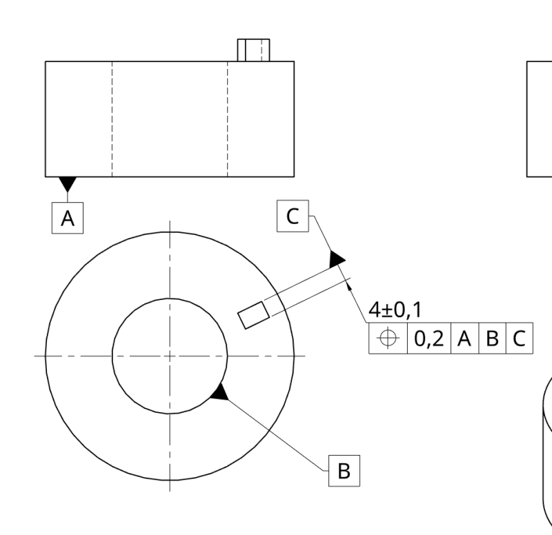
Attached are 2 versions: could the intent be identical? Only to control perpendicularity?

a) - Yes
b) - No -> It goes like this...
c) - What is wrong with you?
d) - answer c) + answer b)

Note that bump is intentionally clocked to relate to actual workpiece as much as it can.
Please tell me if I am missing some theoretical exact dimensions. Are they really needed here?

Screenshot_20200614_133800_eplvjl.png


Screenshot_20200614_131415_reagjr.png

My try would be answer a) I imagine it like if GD&T is the language, drawing with perp is using "simpler/lighter" words and drawing with TP is telling the same thing with "stronger/more sophisticated" words. But it is probably answer d) :)
 
Replies continue below

Recommended for you

Position tolerance defines a tolerance zone which center must pass through the datum axis B. Perpendicularity tolerance does not have this ability. Therefore the two requirements are not equivalent.
 
cr7 said:
Note that bump is intentionally clocked to relate to actual workpiece
Clocked relative to what? Since it's the only distinguishing feature, then it defines the "12 o'clock" angular origin.

John-Paul Belanger
Certified Sr. GD&T Professional
Geometric Learning Systems
 
Perpendicularity should be measured to datum reference A only - adding datum reference B does nothing for the calculation.
Position should be measured to datum reference frame [A|B] - adding datum reference C does nothing for the calculation.

The Position callout will not only control the perpendicularity to A, but also the position with respect to B (how far the axis of B is from the centerplane of the tab).
 
Thanks P.M., thanks Jacob. Where in the ISO 1101:2017 can I read more on what perpendicularity can or can't do?

Jacob Cheverie said:
Position should be measured to datum reference frame [A|B] - adding datum reference C does nothing for the calculation.
Thank you for that, I screw that one up when preparing for posting on forum. So, the question was meant to be formed around that snapshot:
update12_fxjovj.png


Belanger said:
Clocked relative to what? Since it's the only distinguishing feature, then it defines the "12 o'clock" angular origin.
There is actually one more bump to which the drawing is aligned. Sorry for confusion here.
If there only was smaller one I would position it like:
clock6_ki4txt.png

I hope I'm describing the situation clearer now.
 
cr7,

Para. 4.8 in ISO 1101:2017 states:
"- A location specification controls location deviation, orientation deviation and form deviation of the toleranced feature.
- An orientation specification controls orientation and form deviations of the toleranced feature but cannot control its location.
- A form specification controls only form deviations of the toleranced feature."


Table 2 in chapter 5, Symbols for geometric characteristics, shows that perpendicularity is an orientation specification.

By combining the two together, you can conclude what perpendicularity tolerance can and can't do in ISO.
 
Status
Not open for further replies.

Part and Inventory Search

Sponsor