Continue to Site

Eng-Tips is the largest engineering community on the Internet

Intelligent Work Forums for Engineering Professionals

  • Congratulations KootK on being selected by the Eng-Tips community for having the most helpful posts in the forums last week. Way to Go!

Perpendicular callout

Status
Not open for further replies.

Rwelch9

Mechanical
Apr 22, 2020
116
20210107_172616_smhz1d.jpg

Hi

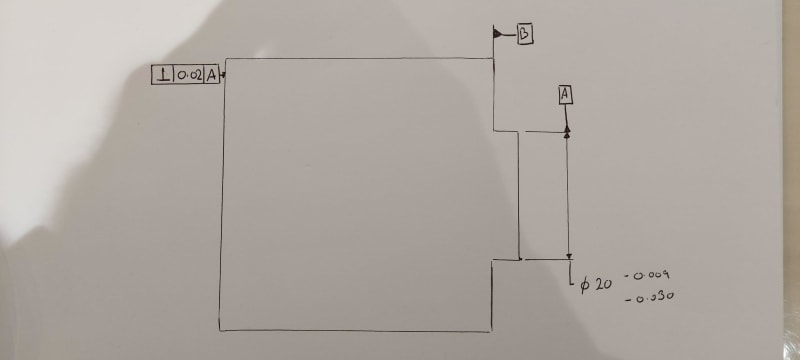
Please see attached sketch.

This is rough sketch of a perpendicular callout. In principle the perpendicular call out here is ok. The issue with measuring purposes although no sizes giving is the length of Datum A axis.

Can anyone explain why you cannot measure the plane perpendicular to B A feature control frame. Due to the axis being so small on Datum A which always causes issues either with manual measurement or with a CMM.

So one solution would be to change the callout to parallel to Datum B although I am wondering if there is another solution.

My thinking is on my CMM I can create a Cylinder which is basically an RAME. This cylinder would be perfectly perpendicular to Datum B and positionally orientated to datum A. I then can check this plane to my created Cylinder which always provides consistent results due to the fact Datum B provides stability in the measurement.

I cannot however change the drawing to suit my methodolgy as it doesn't seem valid. I am working to ASME 14.5 2018.

Does anyone have any suggestions?

Thanks

Ross
 
Replies continue below

Recommended for you

Theoretically you could change the symbol to angularity and reference B as primary and A as secondary. However the question that would remain is - what use has A as a secondary datum reference for the orientation control? It would not be wrong, but B constrains two rotational degrees of freedom out of 3. A as secondary doesn't constrain the third (which is anyway irrelevant for the geometry of the controlled surface). An even more important question is - how is the part held in its functional assembly?
 
Rwelch9,

I assume your drawing is approximately to scale. Your feature for datum[ ]A is a feature of size that allows you to position up and down. It is a terrible orientation feature. The size tolerance is sloppy, and it is short, permitting quite a lot of rotation. How do you plan to figure out its centre line? A feature of size datum effectively is an inspection fixture, and it ought to be around ten times as accurate as the inspected feature(s). What you are showing is legal as per ASME[ ]Y14.5, but very poor practise.

Drafting like this probably shows off a bad design. If you want to control the orientation of the left[‑]hand edge, consider the two shoulder faces, one of which you have tagged as datum[ ]B. These provide a good rotation radius, and you do not have to understand the geometry of a feature of size.

--
JHG
 
Hi, Ross:

You need to pay more attention to quality of datum features. There are four criteria to select a feature as a primary datum. Your feature "A" does not meet them as a primary datum.

You should not talk about cylinder or axis as they do not apply in your case. You can use feature B (CF) or the left face as a primary datum. Then you locate your feature "A" accordingly. Please keep in mind that you don't have axis, but you do have a derived medium plane.

Best regards,

Alex
 
Can anyone explain why you cannot measure the plane perpendicular to B A feature control frame. Due to the axis being so small on Datum A which always causes issues either with manual measurement or with a CMM.

You sort of answered your own question, though its more about ratio of length to width than it is just about the absolute length of a feature. As your width increases relative to the length, form errors (ie: convex) create increasing instability when trying to simulate real features.

For an exaggerated case, I produced a sketch in an older thread - the thread itself is not directly related (indeed is quite long with several side discussions) but if you skip to my post on (18 Mar 19 16:54) in ( you can see the instability created by convex error on a very short but very wide feature. This may be an exaggerated case but imagine trying to reliably simulate a UAME from a feature with any amount of convex error.

As noted above, its important to consider how the actual feature functions and assembles.

My thinking is on my CMM I can create a Cylinder which is basically an RAME. This cylinder would be perfectly perpendicular to Datum B and positionally orientated to datum A.

[...]

I cannot however change the drawing to suit my methodolgy as it doesn't seem valid.

Assuming you change it to a parallelism tolerance like you suggested, what you described is how one would simulate |B|A|. What doesn't seem valid about it? Does it reflect your function/assembly condition?

Side note the term "positionally oriented" is contextually confusing if we consider the word "orientation" by the definition we use in ASME. Also |A| in this case essentially adds nothing to a parallelism tolerance.
 
Jassco,
Datum feature A is a cylinder. There is a diameter symbol preceding the dimension. It's indeed somewhat confusing because there is an axis centerline missing, and datum feature B needs to be depicted by a continuous line.
 
Hi,Burunduk:

I see. Thanks! But the view is incorrect.

This cylinder is too short to be qualified as a primary datum. OP needs to think how he is going "chuck" this part on a lathe. It is not reliable. I don't know what the part actually looks like. Is it a stepped round part or is it a block to a cylinder? If it is a cylinder connected to a block, then he needs to use quality datum feature on the block to "locate" the short cylinder.

Best regards,

Alex
 
Hi all

Thanks for your advice and replies.

I am in complete agreement that Datum A is far two small for a Primary Datum. I should be allowed to change the order to have the Plane as Datum A and the Cylinder as Datum B. This I believe will resemble the functionality of the part as well, I do not design or create the drawings. This is not the actual drawings we work to etc.

Apologies for the my sketch as it seemed to raise more questions than answers.

I am really only interested about the Perpendicular callout to the Cylinder. If the cylinder was 4x a long in length I would have no issue with the measurement or callout.

If the Plane for example was Datum A and the cylinder was Datum B.

Could the perpendicular call out be to a feature control frame of A B ?

I think other option would be to call the other plane for example Datum C and check the cylinder to Datum C.

Thanks


Hi, Rwelch9:

No. You can make the short cylinder perpendicular to A but not to A | B as the cylinder itself is feature for datum B. That would be a dog chasing its own tail.

Best regards,

Alex
 
Alex

I am meaning the plane furthest left on the sketch. Could we have a callout which was that plane perpendicular to A B feature control frame.

Thanks

Ross
 
I should be allowed to change the order to have the Plane as Datum A and the Cylinder as Datum B.
[...]
If the Plane for example was Datum A and the cylinder was Datum B.

Could the perpendicular call out be to a feature control frame of A B ?

It may have gotten buried but both myself and Burunduk suggested this, and pointed out that the addition of the diameter as secondary actually has no impact in this case.

Also the proper callout in this case would also be either parallelism or angularity as your feature is not perpendicular to the primary datum feature.

I think other option would be to call the other plane for example Datum C and check the cylinder to Datum C.

What other plane? And what other cylinder? If you're talking about the short cylindrical feature you're using as a datum feature it should have some relationship to your other datum feature(s).
 
Chez311

I think from your advice, it will be best changing the ordering of the Datums,

I then will add the perpendicularity of the cylinder to the Datum plane.

The plane on the far left I feel would be much simpler just changing to parallelism to the Datum Plane.

Thanks

 
Hi, Rwelch9:

I can't tell what the left side block looks like. You need to locate the larger block and then you relate the small cylinder to the larger block. When I say "locate", I meant "place" it to your coordinate system (XYZ).

You can use any feature you want on the larger block as long as they are most stable.

Best regards,

Alex
 
Status
Not open for further replies.

Part and Inventory Search

Sponsor