Eng-Tips is the largest engineering community on the Internet

Intelligent Work Forums for Engineering Professionals

  • Congratulations waross on being selected by the Tek-Tips community for having the most helpful posts in the forums last week. Way to Go!

Perpendicularity of surface - long edge vs short edge. 1

Status
Not open for further replies.

kwyjibo1

Mechanical
May 10, 2012
6
0
0
US
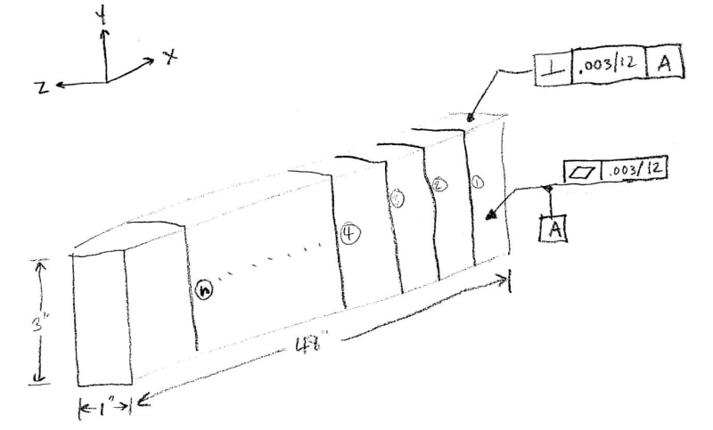
I have a part that I'm trying to have fabricated that has length with width ratio of 48:1 (see image). I'm having trouble specifying a reasonable perpendicularity because of this large aspect ratio. The grind houses say they can only hold .002"/12" flatness on datum A shown (over the 48" length). At any given location along the length (labeled 1, 2, 3, 4, n in my drawing), I really need the top surface to be perpendicular to the front surface within .001". However, I don't really care if the front of the part at location "1" is perpendicular to the top at location "n". If I call out perpendicular within .001", no fabricator can guarantee this over the 48" length of the part. Also, if I call out a perpendicularity of .003"/12" (which could work over the entire length of the part), no fabricator will guaranteed .0003" perpendicularity across the 1" width at the top of the part. I'm looking for a way to say "I need the perpendicularity to be .001" at any point along the length in the x-direction (i.e. 1, 2, 3, 4, etc), but I only need perpendicularity of .003/12 along the entire length".

Can anyone tell me how to explain this on a drawing?[URL unfurl="true"]https://res.cloudinary.com/engineering-com/image/upload/v1690569963/tips/Perpendicularity_Question_j4pbda.pdf[/url]

Perpendicularity_Question_z0t134.jpg
 
Replies continue below

Recommended for you

kwyjibo1 said:
At any given location along the length (labeled 1, 2, 3, 4, n in my drawing), I really need the top surface to be perpendicular to the front surface within .001". However, I don't really care if the front of the part at location "1" is perpendicular to the top at location "n".

I think the numbers refer to this, ctopher.
 
These are just arbitrary locations along the length of the part. The idea is that I'm really most concerned about perpendicularity between the front of the part and the top of the part at any given location (i.e. at location "1"), but I'm not as conerned about the perpendicularity of the front of the part at location like "1" to the top of the part at another location, like "4".

For context, I have a cam follower running along the front of the part, and another one at 90 degrees running along the top of the part. At location 1, I care that the two cam followers are perpendicular to each other (only at location 1). As the part rides along this rail and I get to position 4, I care that the two cam followers are perpendicular to each other (only at location 4). I don't need the front cam follower at position 4 to be perfectly perpendicular to the top surface at location 1 anymore.
 
If the drawing is per ASME Y14.5, you can use the "EACH ELEMENT" notation. This will indicate that each line element is evaluated separately rather than having the entire top surface controlled at once. But the datum will still be established from the entire front surface (the datum will be a plane contacting the 3 highest points along the entire front face).
 
CH,
Straightness is "each element" by default so the note doesn't alter the tolerance meaning in your example.
The fact that you attach the datum feature symbol to the straightness tolerance feature control frame doesn't achieve what you think it does. Attaching it that way only indicates what feature is the datum feature - and that feature is the surface, providing a datum plane. It doesn't change the datum to be each line separately each time.
 
Could the angle between datum A and the top surface be directly toleranced with a note stating the tolerance applies locally?

EDIT: On a side note, the grind house probably won't like applying tolerances locally like this since it's more difficult to measure and probably doesn't really help them meet the spec. Maybe using a restrained condition would help, but that's a discussion to have with the manufacturer.

Ryan.
 
CH,
INDIVIDUALLY won't work either since it is for multiple features. In this case, the OP is dealing with two features - one top planar surface and one front planar surface. For the top surface for example, there are multiple line elements being considered, but they are all part of the same feature.

I don't think that trying to obtain line-element datums from the front surface is a good idea - what will set the precise direction of these line elements (the cutting planes on which these lines will be, will be perpendicular/parallel to what exactly)?

There may be no lazy ways to do it - it is possible to divide the front surface to multiple limited areas by using chain lines and designating each limited area as a separate datum feature. This will also require multiple perpendicularity callouts with different datum reference each time.
It's a nightmare.

 
B,

Realistically, how do you check perpendicularity of very limited area along the long "extruded" part?

You make a flat gauge that looks like letter "L" and "scrape" it along the corner, which looks like Profile of a Line Without Datum control:


And when it comes to using "EACH ELEMENT INDIVIDUALLY" as a datum(s), I've seen much farther extension of principles on this forum.

Nevertheless I am open to suggestions.


"For every expert there is an equal and opposite expert"
Arthur C. Clarke Profiles of the future

 
I apreciate all of the feedback.

Burunduk, I've thought of dividing the part into discreet segments, but as you mentioned, that would be a mess.

CheckerHater, I'm not sure how to even inspect a 48" long part in discreet segemnets. I don't know how to set it up in a free state and do that. Maybe the bar can be placed on our CMM in the orientation where the cross sections I've shown are parallel to a plane that two of the CMM axes makes (like y & z plane, for instance), and then a line can be created on the vertical surface and then the horizontal with the CMM locked in the x-direction. The angle between the two lines could be used to check their perpendicularity. This could be done at various location along the x-axis length of the bar. I don't know if this makes sense or not.


K,

Unfortunately I am not an expert on CMM.

I can imagine you make some measurements (shown in green) to make sure your surface is flat.

Then you can make some measurements along the cross-section (shown in red) to make sure the legs of cross-section are a) straight and b) perpendicular to each other.


Check few more cross-sections as you see satisfactory. Remember - you check profile of the line(s) and you don't have to be perfect - just reasonable.

"For every expert there is an equal and opposite expert"
Arthur C. Clarke Profiles of the future

 
CH,

Yes, that's pretty much what I want to do. Do the "EACH ELEMENT" imply that those dimensions will apply at any discreet location along the 48". I know when they check it here, they will probably only measure at 4 or 5 locations, but I want it to be any 4 or 5 locations.
 
It sounds like you have two separate requirements for perpendicularity.
Can't you just call out both?

Assuming that the elements 1, 2, 3,...n are 1-inch, maybe the picture below will do the trick?

download.aspx
 
Hi, flash3780:

I don't think this will work unless datum surface A is flat. OP asked for what I would call "Local squareness".

Best regards,

Alex
 
Status
Not open for further replies.
Back
Top