Continue to Site

Eng-Tips is the largest engineering community on the Internet

Intelligent Work Forums for Engineering Professionals

  • Congratulations GregLocock on being selected by the Eng-Tips community for having the most helpful posts in the forums last week. Way to Go!

Perth Bridge Collapse - Does Anyone have a theory?

Status
Not open for further replies.

Florian Heise

Specifier/Regulator
Jun 11, 2019
1
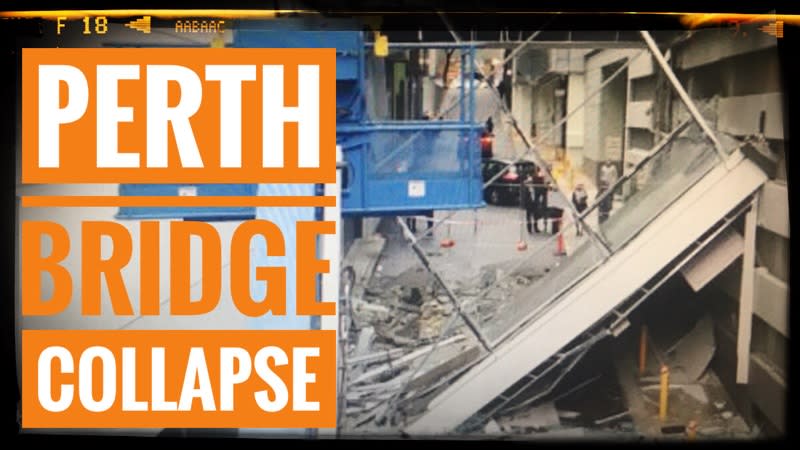
Perth_Bridge_Collapse_olpptc.jpg

Evening everyone, a pedestrian bridge in Perth Collapsed and I was wondering if anyone had any theory or information as to why it might have happened? I've linked to a video I made talking about the collapse.
[URL unfurl="true"]https://www.youtube.com/watch?v=YQIn_XkmSrU[/url]
 
Replies continue below

Recommended for you

To me, it looks like a lack of reinforcing where one would normally expect to see have reinforcing. The bridge looks like it was intended to be supported by a ledge on the left side, but this ledge had no top reinforcing. It was forced to carry the load in shear, which led to the sudden failure.

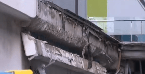
Pause the video at 1:07, close up view in the upper left. You can see the rotated ledge, a right trapezoid shape in cross section, and a diagonal failure plane. There must have been reinforcing in the lower portion of the ledge, which is why it's still hanging there, but it also needed it in the upper portion.

What I didn't see in the article is why the area was cordoned off prior to the collapse. It looks like they were expecting it, and the reason someone suspected trouble would be relevant to the investigation.

Aside: I learned that a trapezoid is called a trapezium outside N America.
 
kipfoot said:
What I didn't see in the article is why the area was cordoned off prior to the collapse. It looks like they were expecting it, and the reason someone suspected trouble would be relevant to the investigation.

They noticed some cracking earlier.
 
I agree with @kipfoot on the poor placement of steel reinforcement. I don't see any steel reinforcement in the top of the left corbel where you would typically see it. The image is dark but it looks like the broken-off corbel is now hanging from all the bottom steel.

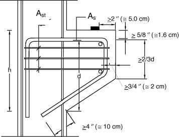
Also the underside of corbels are often sloped back to the support to more closely match the load path which you don't see here. The bottom is just flat. Which would be ok if the corbel was deep enough. But the corbel doesn't look to be deep enough. You can see there is plenty of depth in the supporting floor for the corbel to have been deeper but perhaps the bridge was a pre-manufactured component and they weren't able to change the bearing height without a mismatch in the floor.

Below is a typical corbel configuration and reinforcement. You can see the top steel, the slope of the bottom, and the depth of the corbel in relation to the width of the shelf.

Typical-requirements-for-detailing-concrete-corbel_rlcbu4.jpg


Nice microphone btw. I just got that one myself. Made in Aus I think.
 
Why are do corbel reinforcement details always uses such minimal cover? 5/8? Seems giving them 2" or more of cover would provide them tons more wiggle room to screw it up. It ain't that much more concrete and would be alot safer. Every time I am in a parking deck, I wait for one of these corbels to peel off.
 
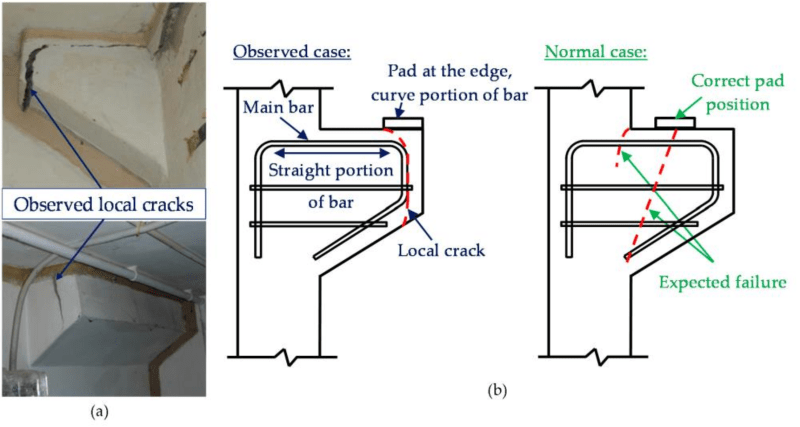
I think the clearances are minimized due to a potential failure mode that goes around the top tension bar. Mode is caused by misplacement/omission of the pad and excessive cover which causes the unreinforced edge of the corbel to be loaded.

fibers-05-00016-g001_bli7ug.png


Also those clearances (5/8") might be for precast which are smaller than for cast-in-place (3/4").
 
Thanks CAB.
That makes sense for the face cover, but not the top and slant cover.
 
Below is a typical corbel configuration and reinforcement.

Slab corbels don't look like that, that's a beam corbel. But otherwise yeah, the lack of top steel is a bit of a problem :)
 
XR250 said:
They noticed some cracking earlier.

More than just some cracking. The corbel is clearly failing prior to the collapse. It's bent down.
 
"Slab corbels don't look like that..."

Our slab corbels for highway bridges look exactly like that.
 
The image above is a heavy beam corbel protruding from a column. It is a different type of element to the failed corbel in the video.
 
Screenshot_from_2019-06-15_16-56-21_puqmyx.png


It is a structural failure at one support side.

It wasn't design as a corbel. In UK we call it a nib. In a standard design design it should have upper and lower reinforcing steel off a standard link or stirrup.

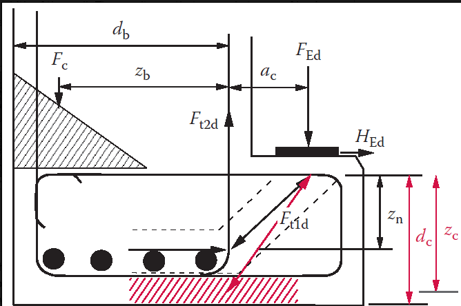
Screenshot_from_2019-06-15_17-05-56_ij2gng.png


The failed nib does not seem to have two layers of rebar. Australian design follows closely ACI from what I have involved in the past.
 
Yes that’s a more appropriate image for the failed corbel in question (or nib or whatever you want to call it). It is standard detail in Australian practice. Often called a corbel.


And yes the top bars appear to be missing, leaving it hanging off the bottom layer. Maybe the top bars stopped short and no one picked it up?
 
Thank you for the region specific input. I didn't mean to confuse by posting the beam corbel details. My aim was to illustrate the typical location of top steel and raise the possibility that the corbel might not be deep enough might have benefited from a sloped bottom.
 
Status
Not open for further replies.

Part and Inventory Search

Sponsor