Continue to Site

Eng-Tips is the largest engineering community on the Internet

Intelligent Work Forums for Engineering Professionals

  • Congratulations waross on being selected by the Eng-Tips community for having the most helpful posts in the forums last week. Way to Go!

Phantom line gages as datum "features"?

Status
Not open for further replies.

Sem_D220

Mechanical
Jul 9, 2018
290
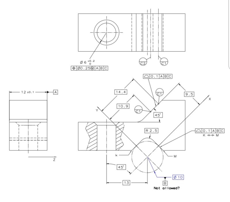
What would be your reaction to a drawing showing a prismatic feature on a part, comparable to those that are found on V-blocks, a phantom line circle tangent to the 2 angled surfaces of the prism, the circle specified with a basic diameter, and a datum feature symbol associated with the phantom line cylinder?

The datum axis derived from the cylinder adjacent to the prism will be used as one of the datums to established a datum reference frame for the part.

The problem I see is that the datum "feature" to which the datum feature symbol needs to be attached and from which the datum axis needs to be derived is not a feature of the part at all, but an external auxiliary component.

Would you be concerned that the scheme is not supported by ASME Y14.5? If it is supported - where and how? If not, what is the closest supported alternative?
 
Replies continue below

Recommended for you

See fig. 4-49 in 2009 for a similar scenario.
 
Thank you pmarc.
I'm aware of 4-49 where a gage sphere is shown with a datum target symbol attached to it and is used to establish a datum point. ASME Y14.5 defines datum targets: "Datum targets are the designated points, lines, or areas that are used in establishing a datum"
Neither spheres nor cylinders are points, lines or areas, but unlike in the sphere case, I don't have a figure in the standard to point to if someone questions the application of a datum target symbol to a gage cylinder shown with phantom line.

The only common way I am aware of to imply the use of a gage cylinder with tangent contact to a surface is to use a datum target line, but datum target lines along the prism surfaces will not serve the same purpose as the virtual cylinder I described.
 
The datum axis derived from the cylinder adjacent to the prism will be used as one of the datums to established a datum reference frame for the part.

More details might be useful here.


The only common way I am aware of to imply the use of a gage cylinder with tangent contact to a surface is to use a datum target line, but datum target lines along the prism surfaces will not serve the same purpose as the virtual cylinder I described.

Cylinders are often (usually?) considered acceptable approximations for datum target lines, and vise versa. Is this not the case for your application?


pylfrm
 
pylfrm said:
More details might be useful here.

Cylinders are often (usually?) considered acceptable approximations for datum target lines, and vise versa. Is this not the case for your application?

pylfrm and others, see details in the image below. This is a made up part drawn to bring an example of a design intent that may require the described dimensioning scheme, and a questionable (in my opinion) datum axis B derived from a gage cylinder rather than from the actual prismatic part feature - which doesn't produce the same datum and would constrain more DOF than intended. Suppose that in functional assembly, a socket head cap screw that will go through the hole will make the part pivot about a cylindrical support represented by the gage cylinder until datum feature C is in contact with the mating part.

pylfrm, considering the figure, does your question about datum target lines still stand?

Screenshot_20190416-125801_Drive_fc55c3.jpg


Edit: I noticed that the degrees of freedom of the part are not constrained well by the datum features geometry in the image above. consider that C datum feature was not parallel to the left side of the prism but at some sufficient negative (clockwise) angle to it. That way translation at the positive X (which is parallel to C) direction would be constrained by the left side of the prism. Silly design mistake [hammer].

Edit 2: the left C1 datum target line at the side view should be C2, as indicated at the top view.
 
Sem,

I fail to see how 4-49 does not provide sufficient extension of principle to allow the use of a datum target cylinder of a prescribed size in your case. With the exception that the notation should replicate 4-49, omitting of course the spherical "S" notation in the diameter. We have had numerous discussions in the past about many other topics which fall under the category of "extension of principle" - in the scheme of things I think this is a pretty minor extension, and I think it follows very logically that it allows a cylinder instead of sphere could be utilized in a similar manner on an analogous part and I'd be surprised if you got significant pushback on that. I'm interested as to why you think 4-49 is not sufficient to support your desired scheme?
 
chez311,
Thanks for the input. I was not thinking in that direction ("extension of a principle").

It is just that even the shown scheme at 4-49 doesn't seem to be supported by the text of the body of the standard. For example para. 3.3.3 "Datum Target Symbol" states: "A radial line attached to the symbol is directed to a target point, target line, or target area, as applicable.". So regarding datum targets, is there a principal to be extended in the first place? Maybe I am being too pedantic here though.

Would you consider applying datum target symbol to B correct (by an extension of a principal based on 4-49) and the shown datum feature symbol B applied incorrectly?
 
Sem,

I see your point, 4-49 is only referenced in the body of the standard in reference to movable datum targets however if we take a strict interpretation of 3.3.3 then figure 4-49 would not be valid. This is actually corrected in the updated Y14.5-2018 para 6.3.3.1 with the verbiage "A radial line attached to the symbol shall be directed to a target point, target line, target area, or other geometry, as applicable."

Sem D220 16 Apr 19 14:30 said:
Would you consider applying datum target symbol to B correct (by an extension of a principal based on 4-49)
Yes

Sem D220 16 Apr 19 14:30 said:
and the shown datum feature symbol B applied incorrectly?
I'll let someone else answer that. My gut says it is incorrect as the analogous notation I see in the standard is 4-35 applied to irregular FOS datums which is not applicable here. The correct method in my mind would be to apply the datum target symbol as described above.
 
chez311 said:
I fail to see how 4-49 does not provide sufficient extension of principle to allow the use of a datum target cylinder of a prescribed size in your case. With the exception that the notation should replicate 4-49, omitting of course the spherical "S" notation in the diameter. We have had numerous discussions in the past about many other topics which fall under the category of "extension of principle" - in the scheme of things I think this is a pretty minor extension, and I think it follows very logically that it allows a cylinder instead of sphere could be utilized in a similar manner on an analogous part and I'd be surprised if you got significant pushback on that. I'm interested as to why you think 4-49 is not sufficient to support your desired scheme?

I fully agree with this. As also mentioned many times before, it's impossible for the standard to cover/show all possible scenarios that one could ever come up with.


Sem_D220 said:
Would you consider applying datum target symbol to B correct (by an extension of a principal based on 4-49) and the shown datum feature symbol B applied incorrectly?

For what it's worth, I would also use datum target symbol instead of datum feature symbol in this case, but I guess I wouldn't make a big deal if the opposed was done.
 
Sem_D220,

I am in full agreement with pmarc and chez311. I will also note that ASME Y14.5-2009 para. 4.24.5 mentions datum target planes, which could be used as further support for the extension of principle.


Regarding your image:

I don't see any problem with datum feature C. The part would rotate about the cylinder axis until contact is made with datum target line C1 or C2. Using two datum target lines to constrain a single degree of freedom like that means only one of them will make contact with any particular part, which seems somewhat unusual, but not wrong.

If you want to avoid the cylinder, you could specify datum target lines B1 and B2 at the basic locations where a cylinder would make contact. Assuming the part is fairly accurate, the result would be very similar. This is what I was getting at with my question, although I do think it would be better to just specify a datum target cylinder.


pylfrm
 
chez311, pmarc, pylfrm,
Many thanks for the input. I am glad that you pointed me to a non-controversial solution in the form of an extension of a principal from a "datum target sphere" shown in fig. 4-49 and as pylfrm noted - "datum target planes" (The components of the mentioned "tangent plane V-shaped datum feature simulator" I suppose?) To "datum target cylinders" (not to be confused with cylindrical datum target lines simulators). It seems that the new standard eliminates all doubts regarding this in para. 6.3.3.1 as quoted by chez311. Thanks chez311, I don't have access to the new standard and it is great to be informed of this update.

pylfrm said:
If you want to avoid the cylinder, you could specify datum target lines B1 and B2 at the basic locations where a cylinder would make contact. Assuming the part is fairly accurate, the result would be very similar.

I was considering that option too but it seems to me that there are some issues that might arise from that scheme - I would appreciate your input on this too. The issues I am concerned about are:

1. A pair of datum target lines placed on the expected contact lines locations between the prism and the cylinder would require a basic distance between the two datum target lines. Fixing them like that does not replicate the behavior of a fixed-diameter single cylindrical gage (or mating part) contacting different produced geometries of the prism at varying distances between the contact lines. That is especially if the prismatic surfaces on a metal part are not as accurate as one could hope since they are not machined (not ideal scenario for a datum feature but nevertheless realistic).

2. Let's suppose that the prism is accurate enough - what type of datum would the two datum target lines B1 and B2 produce? Can a datum axis needed for establishing a DRF as shown be produced that way?

pylfrm said:
The part would rotate about the cylinder axis until contact is made with datum target line C1 or C2. Using two datum target lines to constrain a single degree of freedom like that means only one of them will make contact with any particular part, which seems somewhat unusual, but not wrong.

Initially, I was also thinking of using a single datum target line C1, exactly from the reason that you mentioned, but that too led me to a dilemma:
Datum feature C should produce a "clocking datum" to orient 2 planes of the DRF intersecting at datum axis B (see the X DRF axis shown parallel to C datum plane established from C1 and C2). This is why the established datum from the C datum target(s) should be a plane. Can a single datum target line (edit: in shown configuration) produce a datum plane? If not, how can it set the orientation of the datum reference frame?

Edit: missing word
 
Sem D220 17 Apr 19 04:49 said:
A pair of datum target lines placed on the expected contact lines locations between the prism and the cylinder would require a basic distance between the two datum target lines. Fixing them like that does not replicate the behavior of a fixed-diameter single cylindrical gage (or mating part) contacting different produced geometries of the prism at varying distances between the contact lines. That is especially if the prismatic surfaces on a metal part are not as accurate as one could hope since they are not machined (not ideal scenario for a datum feature but nevertheless realistic).
If you expect significant variation/irregularities on this surface I would agree that a single datum target cylinder instead of the two datum target lines would be the best method. Otherwise as pointed out by by pylfrm if your feature is reasonably accurate then there would little measurable difference either way.

Sem D220 17 Apr 19 04:49 said:
Can a single datum target line (edit: in shown configuration) produce a datum plane?
A single datum target line I think could orient the 2x planes produced by a single datum target cylinder B. If B is instead 2x datum target lines I think the same logic would follow but I am interested to hear others answer to your above #2 as I'm not sure exactly what the DRF and datum planes would look like in that case. Perhaps it doesn't matter as long as the part is fully constrained/immobilized and if the designer desires a specific origin then one can be specified as in Y14.5-2009 fig 4-28. For example in Y14.5-2009 4-48 they show 4x datum planes - are the 3 mutually orthogonal planes that make up your DRF and the origin located at the intersection of the planes coincident with B1/C1 or B2/C1? I don't believe it matters and its up to your inspection to take measurements from a consistent reference. Similarly as it doesn't really matter where the datum planes/origin lie in an asymmetrical pattern specified as a datum.
 
Sem_D220,

I think the whole concept of datums and datum reference frames as defined by ASME Y14.5-2009 is an unnecessary distraction, so I generally ignore it. All that really matters is the relationship between the actual part and the theoretical geometry, and the constraint of that relationship by contact between datum features and datum feature simulators.


pylfrm
 
chez311 said:
For example in Y14.5-2009 4-48 they show 4x datum planes

I believe that the origin of the datum reference frame for this figure can be chosen at any of the 3 intersections between 3 datum planes out of the four, but it is a fairly simple case because wherever the origin of the DRF will be set, the orientation of the planes relative to the part is obvious, as all the datum planes are orthogonal to each other as imposed by the basic orientation between the all-planar datum features. As far as I can tell the standard sets some rules for locating and orienting the datum reference frame wherever a cylindrical datum feature is involved:

4.10.3 Parts With Cylindrical Datum Features said:
A primary cylindrical datum feature is always associated with two theoretical planes intersecting at right angles on the datum axis. Depending
on the number of planes established by higher precedence datums, secondary and tertiary datum axes may establish zero, one, or two theoretical planes.

4.10.4 Constraining Rotational Degrees of Freedom said:
To constrain the rotational degree of freedom of two
planes about a datum axis, a lower precedence datum feature is referenced in the feature control frame.

Then the paragraph proceeds to refer to figures 4-5, 4-6, 4-9 where a secondary datum axis creates an origin and an intersection between two planes of the DRF and a tertiary datum plane sets the orientation of the DRF. For my figure above, in the case of a single datum target line C1 instead of the two shown, perhaps the reasoning should follow fig. 4-9, with the difference that the element through which one of the planes intersecting at B should pass is a datum target line C1 instead of a datum axis C?
chez311, Is that what you meant by saying: "A single datum target line I think could orient the 2x planes produced by a single datum target cylinder B."?

pylfrm said:
I think the whole concept of datums and datum reference frames as defined by ASME Y14.5-2009 is an unnecessary distraction, so I generally ignore it.
pylfrm, that's an interesting approach. Just to make sure I understand it right - is it only the process of establishing a datum reference frame that you find redundant or the concept of datums as well? I can somehow imagine how everything could be narrowed down to datum features (identified by datum feature or datum target symbols) and datum feature simulators being all that is needed to define tolerance zones. I would also be interested to read other opinions on it.
 
Sem D220 said:
I believe that the origin of the datum reference frame for this figure can be chosen at any of the 3 intersections between 3 datum planes out of the four, but it is a fairly simple case because wherever the origin of the DRF will be set, the orientation of the planes relative to the part is obvious, as all the datum planes are orthogonal to each other as imposed by the basic orientation between the all-planar datum features. As far as I can tell the standard sets some rules for locating and orienting the datum reference frame wherever a cylindrical datum feature is involved:

Chez311 said:
Quote (chez311)

For example in Y14.5-2009 4-48 they show 4x datum planes

Some thoughts about fig 4-48 could be found in this thread.


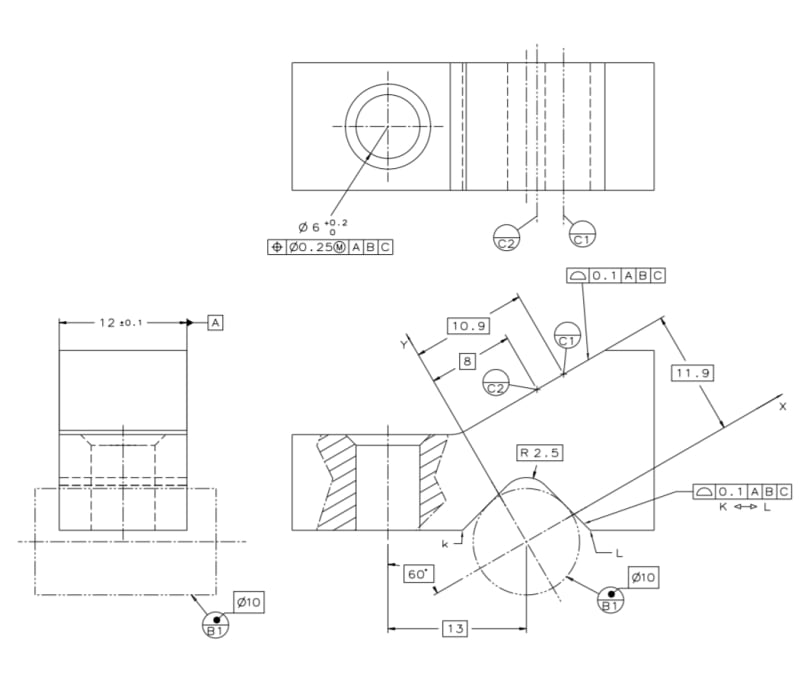
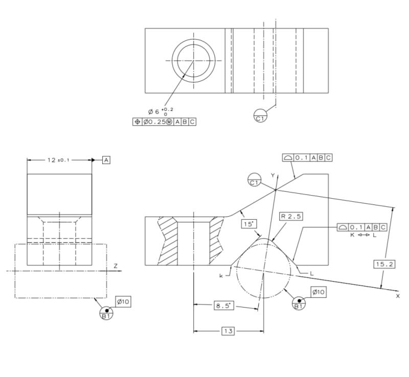
I made two new figures showing datum "target cylinder" B replacing the datum gage cylinder B from my figure above. The angle of the sloped face is now changed to 30° relative to the features shown horizontal at the view (this resolves the issue I mentioned earlier).

Fig. #1 below - tertiary datum feature C designated by two datum target lines and orienting the DRF planes with one of them parallel to the datum plane C created by the datum targets. That is considering that my interpretation of the datum reference plane establishment instructions in chapter 4 of Y4.5-2009 is correct.
Two_dt_yiqn1y.jpg


Fig. #2 below- a single datum target line designates tertiary datum feature C. Not sure what type of datum this datum target line creates (a datum line?). I tried to follow the instructions of chapter 4 here too by the principle imposed by fig. 4-9, and this time the datum reference frame doesn't include a plane parallel to the theoretical surface of datum feature C. I ended up with a DRF I like less even though the gaging set up that will have just one datum target C simulator would be more correct functionally than in the previous case.[ponder]
One_dt_f4vp1g.jpg


Any insight will be highly appreciated.
 
Sem D220 18 Apr 19 05:18 said:
chez311, Is that what you meant by saying: "A single datum target line I think could orient the 2x planes produced by a single datum target cylinder B."?
No thats not quite what I meant, I don't have a good example to point to in the standard except maybe Y14.5-2009 fig 4-32 where the secondary datum feature is offset and orients the 2x datum planes created by the primary datum features parallel to the secondary datum centerplane instead of having to pass through it (in your example they are secondary/tertiary datum features). The tertiary datum plane would be coincident with the surface that C1 contacts, as in the datum plane created by B1 (a single datum target line) as well as B2 (also a single datum target line) in 4-48.

Regardless I think such distinctions are probably what pylfrm called "unnecessary distractions" - also thanks to greenimi for the link to that thread. I think that thread pretty much echoed what I said about the arbitrary nature of the location of the actual location of the origin/DRF as well as what pylfrm alluded to, especially in the quote from Evan below. He utilized a symmetric bolt pattern as an example instead of an asymmetric one which still accomplishes the same thing, I just use the asymmetric example because theres no obvious "center" (or perhaps less obvious - as there is a locus) that one can point to.

axym 24 Feb 19 19:37 said:
This example also shows, however, how confusing and arbitrary Y14.5's concept of datum planes can be. It was built from simple datum feature combinations, where a three-plane XYZ coordinate system can be placed in a reasonably obvious way. In more complicated examples such as in Figure 4-48, part of that arbitrary nature is acknowledged (for stepped surfaces, the datum plane should contain at least one of the datum targets). In even more complicated examples such as Fig. 4-26 with the hole pattern datum feature, the origin of the DRF can be put at the center of the pattern or at any other location defined by basic dimensions. In other words, the placement of the "datum planes" and DRF origin are completely arbitrary. The only thing that really matters is the mutual relationship between the datum feature simulators.
 
Sem,

Just saw your post after I submitted that. My response still applies, I think the DRF could look the same between both of your figures.
 
chez311 said:
The tertiary datum plane would be coincident with the surface that C1 contacts, as in the datum plane created by B1 (a single datum target line) as well as B2 (also a single datum target line) in 4-48.

chez311, do I understand correctly that the C1 datum target line in my figure #2 should create a datum plane passing through it and oriented at 15° basic to the left side of the datum prism? And that this is essentially the same C plane as in fig #1, which orients the datum reference frame the same?
 
Sem,

Yes, that is what I would consider the "default". Again, without reiterating what I've already said and in the thread referenced by greenimi it is all pretty arbitrary. If you don't like what you or others might consider the "default" location/orientation of the DRF you can locate/orient it with basic dimensions as per 4-28.
 
Status
Not open for further replies.

Part and Inventory Search

Sponsor