Continue to Site

Eng-Tips is the largest engineering community on the Internet

Intelligent Work Forums for Engineering Professionals

  • Congratulations waross on being selected by the Eng-Tips community for having the most helpful posts in the forums last week. Way to Go!

Pile Loads Under Reinforced Concrete Pile

Status
Not open for further replies.

Rajshrn06

Civil/Environmental
Jun 29, 2020
11
Hi

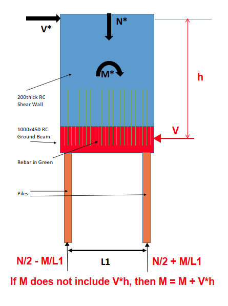
I have a question regarding a RC shear wall supported on Steel Piles. Please see link for shear wall and pile configuration.

When a lateral load is applied to the shear wall, there is overturning moments on the wall in addition to shear and axial loads. If we assume that all of the rebars yield, would this mean that my ground beam would need to be designed for uplift due to yielding of rebars with compression being confined to the far end? This is basically the case where we already account for axial load in calculating moment capacity and there is a localised very high compression load on one end of the beam/wall; Or do we need to also apply downward axial force(N*) which would then counteract the tension force due to rebar yielding.

In addition, what forces would the pile experience? To obtain pile loads due to Moment, do we do M*/L1 or do we do M*/ lever arm of couple. The lever arm of the couple would almost be equal to L1/2 with compression block at one end and tension over most of the ground beam. The latter would give me a much higher compression load in the pile.

Also, how do we deal with this when there is a 3rd Central pile?
 
 https://files.engineering.com/getfile.aspx?folder=952ebd11-773b-4bb5-9377-47e5e0454188&file=200thick_RC.pdf
Replies continue below

Recommended for you

I usually don't pay much attention to that... I take the axial loads, the shear and the overturning moment out at the piles/caissons. With a small building the loads on the dowels are minimal (and, to me, negligible) on a big building, other than the dowels adjacent to the supports, they are likely tension members from the vertical load.


Rather than think climate change and the corona virus as science, think of it as the wrath of God. Feel any better?

-Dik
 
Why would you assume all bars yield? Design them so they do not yield. The diagram below indicates pile load based on the applied forces shown. I don't know whether or not V*h is included in M.

image_xrlvb6.png


BA
 
If they don't yield, you have too many of them...[lol]

Rather than think climate change and the corona virus as science, think of it as the wrath of God. Feel any better?

-Dik
 
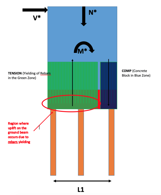
Thanks Ba and Dik. Ba, sorry, what I meant was that all rebars in the tension zone yield. I believe your load diagram shown would be valid for linear elastic members such as a Pure steel plate shear wall, where the centre of rotation of the moment arm is exactly at the centre with uniform compression on one side and uniform tension on the other side. With the RC wall, majority of your rebars distributed along the length of the wall will yield to balance the compression force, say for a very high applied moment. The rebars have been developed in the ground beam so I feel it would apply uplift force on the ground beam when it yields as shown below. If the yielded rebars were somehow lumped into the pile directly then I believe the ground beam won't experience any load and your load distribution will be how I would imagine it to be.

To discuss this further, let's say if we have a 3rd central pile, since the central pile is situated in the tension zone, I presume this pile would experience uplift also? If this was a pure steel plate shear wall, then the load on this pile would be N*/2 and the end piles N*/4+-M*/L1, but I do not see this to be the case for an RC wall.

Your thoughts? Am I overthinking this?

Screen_Shot_2021-06-16_at_7.30.02_am_eqqtnl.png
 
The stress in the bars between grade beam and wall has zero influence on the pile loads. The wall and beam can be regarded as a rigid body which is attached to a pair of piles as shown in your first sketch, or three piles as shown in your latest sketch.

In the case of two piles, the load on each pile is found by statics, which is shown on my earlier sketch. That is valid for any value of M or N.

If a third pile is added, the pile loads cannot be determined with precision. Under pure gravity load, and assuming all piles are equal, each pile will tend to carry N/3. Add a little moment and the outer piles will carry N/3 + or - M/L. Increase the moment to the point of collapse and either the compression pile will fail, throwing more compression into the middle pile, or the tension pile will fail, throwing tension into the middle pile. It depends on the ration of M/N.


BA
 
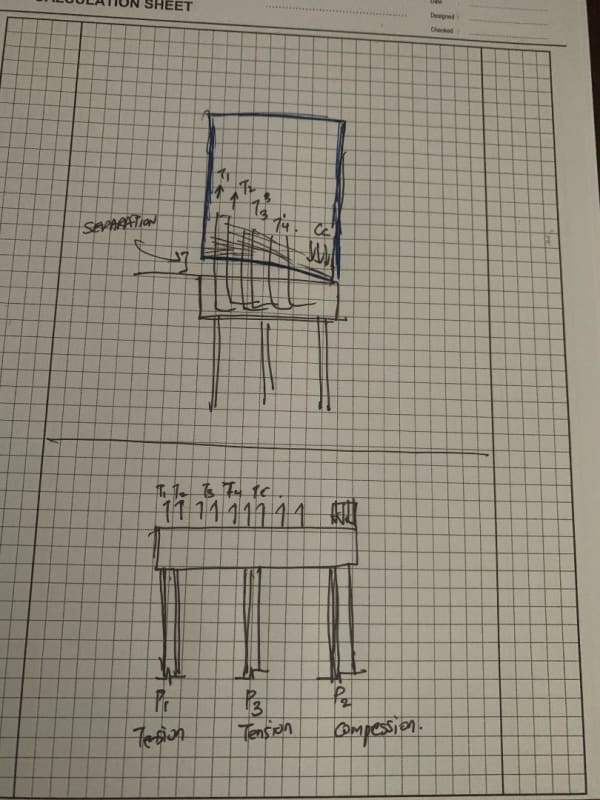
Agreed that the wall and ground beam act as one rigid body, but this is only possible through the anchorage of reinforcement as the concrete would crack in the tensile zone. When overturning moment is applied, the wall would try and separate from the ground beam and this separation will be resisted by the rebars alone. In this case the rebars would try and pullout of the ground beam and cause the uplift directly on the ground beams. Wouldn't this yielding and uplift then be transferred to the piles? If we draw a free body diagram, this is how it will look?

Henceforth in actual, the ground beam, wall and pile all act as a single rigid body?

thumbnail_rksovu.jpg
 
No! The grade beam and wall are tied together with bars. Either the bars are adequate to resist the applied moment or they are not. If they are not, some or all of the bars will yield. Actually, the wall, as drawn, appears to be a deep beam, so normal beam theory will not apply, but that is a subject for another thread. If the bars are adequate, the applied forces are applied to the piles at three discrete locations. Those forces are not affected by stress in the bars between grade beam and wall. That is an important point.
Equilibrium at the top of piles is independent of equilibrium at top of beam.

If the applied moment is sufficient to cause tension in P3, then the compression in P2 is greater than N/2 + M/L1, which was found in the earlier case of only two piles. So what was the point of adding P3? It makes no sense.

BA
 
Raj06,

For equilibrium, a horizontal reaction is required to balance the applied force V*. Piles cannot provide much lateral resistance, so there must be another source of lateral resistance. The top of pile elevation is one meter lower than top of grade beam, so the net moment will be greater at t.o.p. than t.o.g.b. by approximately 1000V*, assuming the c.g. of reaction is at t.o.p.

BA
 
Status
Not open for further replies.

Part and Inventory Search

Sponsor