Eng-Tips is the largest engineering community on the Internet

Intelligent Work Forums for Engineering Professionals

Pin Connected Gusset Plate Uniform Force Method

Status
Not open for further replies.

zrck99

Structural
Dec 19, 2014
82
0
0
US
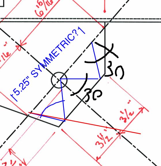
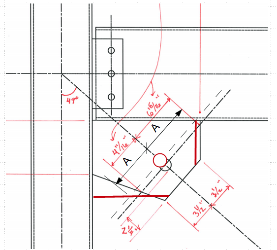
I am designing some braced frames which use rod x bracing. Where the tension rod meets the gusset plate, I plan on using a 3 1/2 clevis with a 1.75" Dia A36 pin. I can size the gusset plate geometry based on the uniform force method but I'm running into issues with the Pin connected member dimensional requirements. D5.2(a) says, "The pin hole shall be located midway between the edges of the member in the direction normal to the applied force." The attached sketch shows my dimensions as well as that code section. Do you guys have any suggestions for how to make these two requirements work together?

Also, in the AISC Example D.7 pin connected member design example, after doing their pin connection checks, they do a tensile yielding check on the full gusset width. In their example, the pin hole is centered in the gusset and they check tensile yielding across the full width of the plate. In our case would you agree with using our full 4 11/16" + 6 15/16" = 11.625" width for a yielding check? I would think of using a Whitmore Section but with only one hole I'm not sure how to go about that. The example problem is attached and pertinent areas clouded for reference.

Thanks.
 
 https://files.engineering.com/getfile.aspx?folder=73882c5b-069a-4ac9-b0b4-8968fd1751ee&file=attachment.pdf
Replies continue below

Recommended for you

I would:

1. Check bearing on bolt hole
2. Check shear along line CD
3. Check tensile strength against surface along line AB

 
Here is the sketch.

image_oferfr.png
 
retired13,

Do you think that the requirement to center the hole in the connector plate width is not critical in this application? I guess I'm just wondering why that requirement is in there and if it could have any negative consequences on the Uniform Force Method producing zero moments at the connection surfaces.
 
IMO, rather than saying it must center on the edge, it shall state that the off center force might induce unbalanced force in the plate, especially for the well shaped rectangular plates. For irregular plates, to me, it is important when you check global plate stiffness, and design the connection welds. My sketch above actually was in a manner similar to design for the block shear.
 
zrck99 said:
Do you guys have any suggestions for how to make these two requirements work together?

My read on the "midway between the edges of the member" is that the "member" is the brace itself and not the gusset. So no conflict there.

zrck99 said:
In our case would you agree with using our full 4 11/16" + 6 15/16" = 11.625" width for a yielding check?

I wouldn't as I feel that there's an inherent eccentricity that's not been accounted for there. But, then, what should one do? I've proposed something below that I feel would be reasonable, kind of considering an Whitmore spread on the way out in compression and then back in tension to create a symmetrical width about the pin. Hopefully someone will chime in with a more definitive recommendation.

C01_bmksiu.jpg
 
retired13, why would the shear check along CD be inclined 30deg? The critical section for shear here would be in line with the load and perpendicular to the edge of the gusset - your line CD is 15% longer than the critical section.

zrck99 said:
I guess I'm just wondering why that requirement is in there and if it could have any negative consequences on the Uniform Force Method producing zero moments at the connection surfaces.

This won't change anything in the UFM. That method depends on the brace angle, length gusset on beam/column, beam/column depths, etc...what is happening near the free edge of the gusset doesn't matter for what you're focused on when you're going through the UFM. It's also worth noting that you don't have to have zero moments. UFM provides a means of dealing unbalanced geometry generating moments in the gusset - you should take advantage of that because it can sometimes provide a more economical connection. Sure it's nice to have everything perfectly balanced, but if "good enough" is cheaper/easier than "perfect" then it is the better solution.
 
retired13 said:
Straight line is quite conservative, 45° will be too liberal, IMO, 30° is more just.

Respectfully disagree. To be clear, when you're evaluating shear along lines CD, you're checking block tear-out. The gusset is going to fail in a manner that requires the least amount of energy - it will take the path of least resistance. Intuitively and mathematically that puts the failure plane in line with the load and perpendicular to the plate edge.

If you feel the straight line is quite conservative I would love to hear the reasoning behind it.
 
Hey all,

The attached sheet is from the AISC section on Pin Connected Members. It looks to me like the clouded check is looking at the shear that CANPRO/retired13 have been discussing.

Based on that, I will just set the plate dimensions at column/beam based off of Uniform Force Method and ignore the equal width requirement. I can meet the D5-1 Eqn and D5-2 Eqn so as long as I'm not screwing up the UFM zero moments by the pin hole being unequally spaced I should be good to go.

I appreciate everyone thinking this through with me.

ZRC
 
CANPRO said:
If you feel the straight line is quite conservative I would love to hear the reasoning behind it.

Human909's photo is quite convincing for straight line failure thru bolt holes in tension, an classic/un-arguable block shear failure mechanism.

I've no way to prove that the gusset plate failed by a single bolt is any different, but it is interesting to note that the shear failure seems to be initiated at an angle other than along the force, evident by mechanics and figure below, although the stress will find weak plane and turn to vertical ultimately (that prove me wrong). A well construct FEM can tell the story better.

image_sky1ag.png
 
Status
Not open for further replies.
Back
Top