Eng-Tips is the largest engineering community on the Internet

Intelligent Work Forums for Engineering Professionals

Pinned connection of composite beams to shear walls

austinb98

Structural
Aug 24, 2024
17
1
3
TR
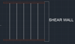
When I put the composite beams between two steel beams connected to the shear wall as seen below, the P-M-M ratios of the steel beams are high. This is the example in the first picture.
1729888814264.png
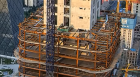
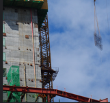
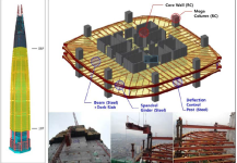
In the second picture: Connecting these beams to the walls creates the following problems. To connect steel beams to bulkheads in this way, a large number of steel plates are required. In addition, these beams are connected to the walls in a way that creates a moment on their weak axes.
ee
The building in the picture belongs to the Lotte Tower building. What I want to explain is how correct it is to connect composite beams to walls in this way. (I think these beams have moment transferring connections, they are not pinned)

Which method do you find more accurate?
 
Last edited:
Replies continue below

Recommended for you

I'm not too familiar with high rise design. But in low rise design, most people generally use beams with pinned connections. In high rises, it may be valid to use a moment connection to engage the inner core with the outer shell in an outrigger type of configuration, which has vastly different implications for story drift. Honestly, I don't know much about the specifics of the outrigger method (like how the moment is transferred in practice), but I think it's valid.

In conclusion...I don't really know what question you're asking. I read your post like 5 times. Can you clarify it in a nutshell of A versus B?
In the first image, there are steel beams constantly connected to the shear wall. There are composite secondary beams between these beams.The loads of the secondary beams are taken by the steel beams located outside.
The second image (taken from the real building) shows that the secondary beams are directly(continuous) connected to the shear wall. I don't know the type of connection (pinned or continuous), but in this way, the load on two beams in the first image is distributed to many beams in the second image. This reduces the P-M-M ratios and cutting rates of the beams.
There are some advantages and disadvantages between these situations. Based on these, I wanted to ask which application do you think makes more sense for high-rise buildings? For example, in the second image, it will be necessary to leave many steel plates on the curtain. (for connecting steel beams). It will be necessary to adjust their positions and angles well. Many problems may arise.
 
Trying to summarize what you're saying:

Image 1. A few girders are used, which are probably pinned. There are secondary beams (let's say composite beams) between them.

Image 2. Long span beams are used, which may be pinned or have moment connections.

Based on this, I'd say Image 2 (long span beams without secondary infill) is more efficient. If you can choose between short beam/long girder or long beam/short girder, the second option (long beam/short girder) tends to be more economically viable. I would rather have a bunch of 10 kip self dead load beams instead of two 100 kip self dead load beams. The reasons are:

A. Total weight of steel or concrete will be less.
B. With the heavy girder approach, you are concentrating the failure scenario into two points.
C. You need a heavier crane for dealing with larger girders.
D. Multiple long beams spread out the load instead of concentrating it into two points, which has increased chance of bearing failure.

This determination isn't changed whether you have a high-rise or not. The loading onto the shear walls and perimeter beams is exactly the same in either scenario, but the one with the long beams is more efficient and more "structurally redundant" (hopefully you understand what I mean by that).
Thanks for the replies. In the second case, there is a problem: The beams are connected to the shear wall from many points. We like and want the beams to be connected to the shear wall through their strong axes. Because it is not good against forces coming along the weak direction of a shear wall. In this case, I am thinking of designing the secondary beams to be connected with shear wall pins. In this way, moment transfer will be only with the main steel beams. However, my only fear is creating shear forces and torsional moments in the weak axes of the shear wall. Another example of the second case is a high-rise building. citic tower
ff
 
These kinds of infill beam to wall connections are typically:

1) modelled as pinned and;

2) detailed to keep end moments modest.

As a result, to my knowledge, designers will not explicitly consider the weak axis moments induced in the supporting walls.

I disagree that embed plate shear connections are problematic. When designed to accommodate reasonable tolerances, and installed by competent personnel, it's proven to be a cost effective and relatively trouble free approach.
Thanks for the reply. It may be a pin connection. My fear is that the axial forces coming to the shear wall will still occur in pin connections. On the problems that may be caused by these axial forces coming from the weak side of the shear wall.
Additionally, the beams connected to the shear wall in the pictures are not pin connections. Because in this case, which element will transfer the moment between the shear wall and the columns?
 
Additionally, the beams connected to the shear wall in the pictures are not pin connections.

I doubt that but it's difficult to tell from the photos. Do you have any photos that show those connections more close up?

My fear is that the axial forces coming to the shear wall will still occur in pin connections.

Put that fear aside. The diaphragm will absorb any in plane deck forces and prevent them from being transmitted axially through the beams.
 
I doubt that but it's difficult to tell from the photos. Do you have any photos that show those connections more close up?


Put that fear aside. The diaphragm will absorb any in plane deck forces and prevent them from being transmitted axially through the beams.
I was able to find these from another building. But in general, what I noticed is that they are done in a similar way.

 
Let's just assume that the beams are moment-connected to the shear walls. This is quite difficult to do, and I share the same doubts as KootK. But for the purposes of answering your question, I'm assuming you're correct in your assumption that the beams are moment connected to shear walls. In that case, I think the reason this is done is to engage the perimeter columns and beams in the lateral system to reduce the seismic and wind drift using the outrigger effect. Here's an article that touches upon how that works: https://www.scielo.cl/pdf/rconst/v22n2/0718-915X-rconst-22-02-337.pdf

I don't think it would be done to increase end fixity to reduce positive moment. The difficulty of designing and fabricating that connection, and the problems it causes in shear wall minor axis bending, would not be worth it for the gravity system. It can only make sense as part of the lateral system. (Of course, maybe I'm wrong and I'd love to hear an opposing opinion.) There is a building designed by SOM back in the day that engages the perimeter in this way by using a thick flat concrete slab, though I forgot the name of that building.
 
It is difficult to moment connect these kinds of beams to a core wall. Often these connections have cleats with horizontally slotted holes to allow for installation tolerances and movement of the core, which also releases them axially. The concrete slab above is relied upon for diaphragm forces. Some small out of plane bending occurs at the wall due to local eccentricity of the shear which is generally applied at the face of the wall or some small distance away depending on the configuration of the connection (usually a T bracket).
 
Back
Top