Continue to Site

Eng-Tips is the largest engineering community on the Internet

Intelligent Work Forums for Engineering Professionals

  • Congratulations KootK on being selected by the Eng-Tips community for having the most helpful posts in the forums last week. Way to Go!

Pipe stress slightly high in sustained case 3

Status
Not open for further replies.

tsarbomba_imported

Mechanical
Apr 17, 2017
11
The pipe stress is slightly higher at ratio of 1.05 times the allowable in sustained case. Since the factor of safety is 3 in B31.3 piping code, is this wrong way to analyze the pipe? Due to constraints in space, it is really difficult to input any supports and the cause is due to low axial stiffness of expansion joint not supporting the adjoining miter bend. Please let me know if my information is not sufficient to answer the question.
 
Replies continue below

Recommended for you

You are the responsible piping engineer and thereby empowered to use (or not use) the tools available ...

Personally, I would investigate the stiffnesses of the pipe supports and nozzles and adjust accordingly if you are that close to passing

.... Just because CAESAR-II defaults to 1.0E12 for a nozzle stiffness does not mean that it represents your particular installation

There are others who will strongly disagree with me based on their false god of "Conservatism" .... bullshit I say .... Bullshit !!!!

MJCronin
Sr. Process Engineer
 
If it’s caused by a hot sustained case and you have a slight lift off in the hot case for a support at that spot, that ligt off (provided it’s small, say 1/26”) may disappear over time and sort shakedown itself to a lower stress state.

Huub
- You never get what you expect, you only get what you inspect.
 
tsarbomba, What do mean by "low axial stiffness of expansion joint"?

Have you looked a different type of bellows with tie rods/hinges to carry the pipe weight.

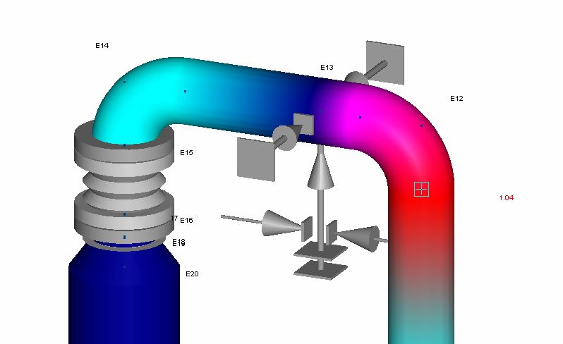
A screen shout of your piping model would be useful.

 
%E3%82%AD%E3%83%A3%E3%83%97%E3%83%81%E3%83%A3_x5hnmw.jpg


The operating condition is fine even though there is liftoff in the pipe.
The loads on the supports and nozzle is very high but the pipe is 600A pipe.
By low axial stiffness of expansion joint, I meant I cannot use any other expansion joint other than what I have right now. It does not have any tierods or hinges. Since the pressure is FV, there is no problem of pressure thrust. My only problem is the elbow has large stress and I am guessing it is because the pipe above the expansion joint is too heavy and there is too much bending moment in the elbow on the other side. Any input would be very helpful.
 
FV is, for pressure thrust, the same as 1 bar(g) pressure. So you do have pressure thrust, but only opposite (in terms of forces - physically more like a suction).
What's a 600A pipe?

And how does your support look like in real life? Do you have a drawing or photo of an example?

Huub
- You never get what you expect, you only get what you inspect.
 
It is too difficult to make suggestion without seeing full picture. I am not in favour to use an expansion joint on top of the nozzle and a rigid support very close.
There might be a way to eliminate the expansion joint and relocate the support, and change support type to reduce the differential thermal expansion on the pipe between vessel and support location.

I guess the system needs a quick overview by a pipe stress engineer to eliminate all the conflicts.
 
You say the loads on the nozzle are very high - are they acceptable per the vendor/equipment provider?
If the nozzle loads are high and you're using an unrestrained expansion joint with pressure thrust - is the expansion joint even getting you anything in this application?

I'm not sure what all you have going on in the middle section of your picture, but is a spring hanger/spring can not an option? A support that travels with the pipe may get you below the allowable code stress for the sustained.

In my opinion, even with the safety factors in the code, you need to get the sustained code stress less than the allowable. That's why allowable stresses are defined. If this is an emergency situation, maybe this is suitable as a short term fix, but it doesn't sound like a long term solution.
 
@tsarbomba

To reiterate what others have said, a more complete picture of the situation would be helpful.

Is this a new piping installation? A retrofit where you are attaching a vessel and expansion joint to an existing line?

What is the piping configuration below this mitered elbow? Can we get a more complete screenshot of the 3D stress model?

What pipe supports do you have currently selected in the middle section? Looks to be guides and limit stops?
 
As I see it, the vacuum pressure is pushing down on elbow E14 and causing bending at E12. move the support closer to E14 to reduce the moment arm.

Without understanding your process and application hard to say if you have the correct type of bellows and piping arrangement.
 
Status
Not open for further replies.

Part and Inventory Search

Sponsor