Continue to Site

Eng-Tips is the largest engineering community on the Internet

Intelligent Work Forums for Engineering Professionals

  • Congratulations KootK on being selected by the Eng-Tips community for having the most helpful posts in the forums last week. Way to Go!

Plate bending 1

Status
Not open for further replies.

TheLizard

Structural
Mar 5, 2021
1
Good afternoon engineers

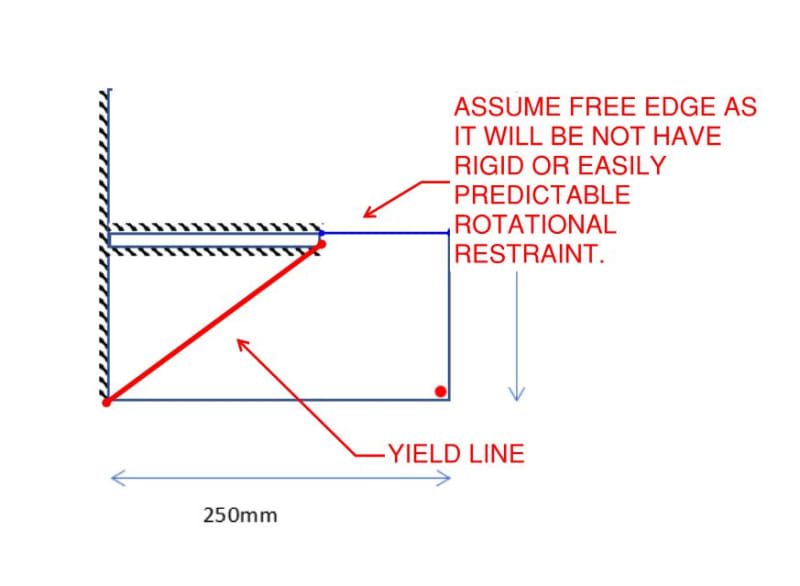
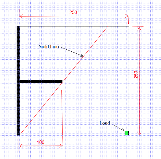
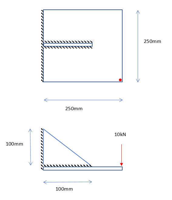
I have a built up plate connection with a point load on one corner potentially.
I have tried to analyse elastically with a 10mm strip to the stiffener but this requires a very thick plate.

Normally I would extend the stiffener to the edge but the client has stated there is a clash.

Please can you advise on a suitable yield line?

Your thoughts are greatly appreciated
Screenshot_2021-03-05_162905_dcid8n.png
 
Replies continue below

Recommended for you

For my money gussets or stiffeners need to be very close to anchor bolts, point loads etc, lest the load path pass thru a trampoline, diving board or cookie sheet.
 
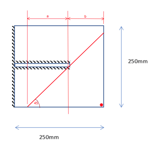
I would think the yield line would be more as shown below:

image_fpr4t0.png


BA
 
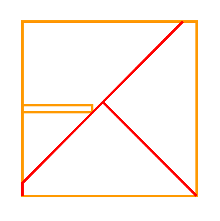
BART: to be more clear... both those yield lines are possible...

Rather than think climate change and the corona virus as science, think of it as the wrath of God. Feel any better?

-Dik
 
dik,

That is not more clear. It is less clear. I have shown only one yield line, namely the thick red line at 45[sup]o[/sup] to the edge of plate.

What other yield line are you referring to...KootK's? If so, how is that possible?

BA
 
He's saying there are an infinite number of possibilities, you've presented one, he's presented another. One pattern proposed might be the actual true caoacity where lower bound and upper bound solutions are equal, neither might be.

Yield line theory is an upper bound solution by its very nature. So the true collapse load is always lower unless you happen to guess or solve for the actual critical arrangement. You're both guessing is the point, with no numerical justification apart from what 'feels' correct.
 
It depends on where the plate buckles first.
I could imagine the first yield line running from the gusset straight out to the edge (along the line of the gusset). And then further defection would be along the line KootK drew.
Could you gusset above or below along the edge where the load will be?

= = = = = = = = = = = = = = = = = = = =
P.E. Metallurgy, consulting work welcomed
 
Agent666 said:
He's saying there are an infinite number of possibilities, you've presented one, he's presented another. One pattern proposed might be the actual true capacity where lower bound and upper bound solutions are equal, neither might be.

Well, there may be an infinite number of possibilities, but there is only one correct yield line, and that can be proven theoretically.

Agent666 said:
Yield line theory is an upper bound solution by its very nature. So the true collapse load is always lower unless you happen to guess or solve for the actual critical arrangement. You're both guessing is the point, with no numerical justification apart from what 'feels' correct.

I agree that yield line theory is upper bound, but there is justification for an angle of 45[sup]o[/sup] in this case.

BA
 

Not KootK's, this would have to have a different pattern for continuity, but bending straight across, depending on the geometry... as far as an infinite number of solutions, being a finite individual... I won't live long enough to appreciate them... also, due to the molecular structure... there are a finite number, if you want to be picky... I was trying to be humourous... whether you meant to or not... you showed two viable patterns.

Rather than think climate change and the corona virus as science, think of it as the wrath of God. Feel any better?

-Dik
 

Koot's is just part of the yield pattern and has to be finished to maintain compatibility with the rest of the plate... there would be additional hogging and sagging yield lines for it to happen... and the load would be substantially increased... it would not be a lower bound for yield.

Rather than think climate change and the corona virus as science, think of it as the wrath of God. Feel any better?

-Dik
 
BA keep in mind the original sketch is woefully out of scale, the stiffener is only 100mm long, vs plate length of 250mm.

Still think the critical yieldline will be at 45 degress? I don't having sketched out a 45 degree yieldline, but I'm first to admit I am purely just guessing based on drawing it out to scale.

Somewhere along the way engineers seem to have lost the ability to convey information to scale, and scale matters most of the time in interpreting a particular problem that involves geometry.

image_clzn9m.png
 
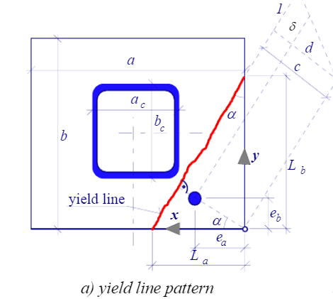
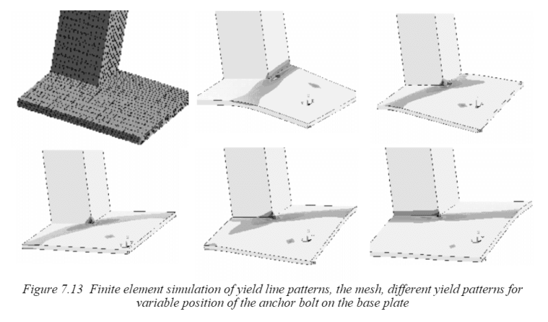
I'd imagine there are some parallels with the case of a single bolt loading a corner of a baseplate with a hollow section attached. Slight variations in the load position can cause quite different yieldlines to become critical. For example:-

image_edrtjh.png

image_x2nybv.png
 
Agent666,

I had not noticed that the drawing was so much out of scale. Should have looked more closely. I now believe the yield line will be in the location I have shown below.

image_n58a6y.png


BA
 
Is the point load lifting up, or pushing down on the corner?

What is the configuration of concrete (?) under under the whole plate, and how far does the concrete (?) extend in all directions? That is, is the concrete resisting the point load (if it were pushing down) at the edge of the plate? Or is the plate being pulled up and the presence, (or absence) of the concrete under the plate irrelevant?
 

I try to avoid gusset plates... it's generally less costly to thicken the baseplate... and, I've often seen gusset plates attached to the face of HSS sections.

Rather than think climate change and the corona virus as science, think of it as the wrath of God. Feel any better?

-Dik
 
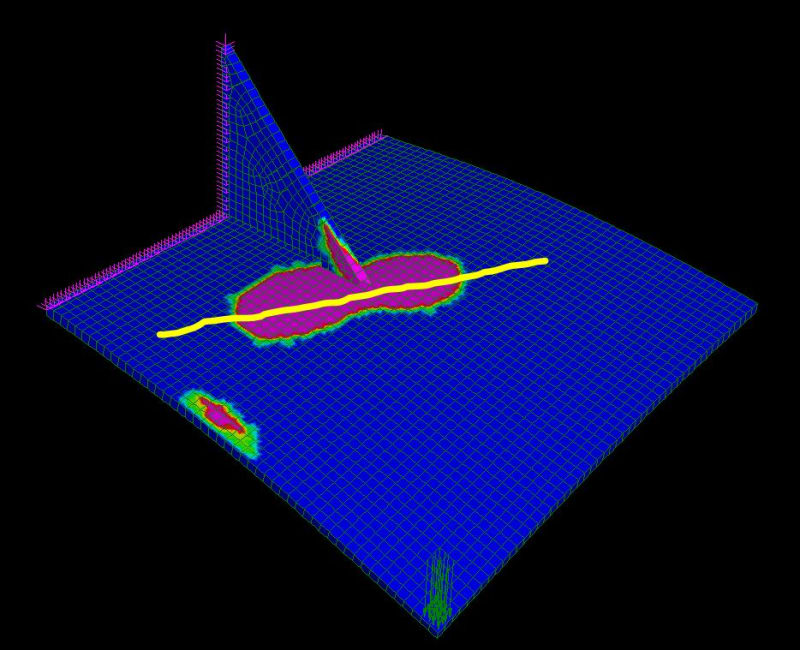
I knocked up a very quick FE model of this. I won't pretend that this is necessarily very accurate or revealing.

I have taken a guess at the plate thickness (6 mm) and material strength (250 MPa), but this shouldn't make any difference to where the yield line occurs.

First picture shows the yield line at approx. 45 degrees, starting near the tip of the stiffener. Pink areas have reached yield stress.
Capture_jsylnz.jpg


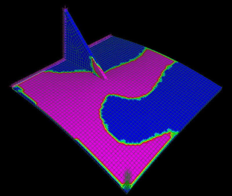
Second picture is at a higher load where the yield line is across the whole width of the plate. It also seems to be more straight across than the original 45 degrees. But there is also a lot of yielding locally around the point load and all along the nearer edge of the plate.
Capture3_bw1txz.jpg
 

Can you post the essay?

Rather than think climate change and the corona virus as science, think of it as the wrath of God. Feel any better?

-Dik
 
It will bend about the tip as others have shown.

Make sure the tip stresses aren't too high, or it might peel off the stiffener.
 
Status
Not open for further replies.

Part and Inventory Search

Sponsor