Dear David,
Plate/Shell elements are devoted to mesh the midsurface of a solid, and the thickness goes half to top & half to bottom fiber.
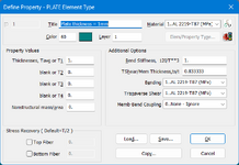
You have
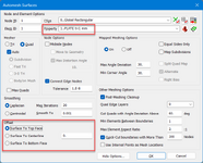
OFFSET option in the mesh > mesh control > attributes property for surfaces command: this will allows to mesh either the top or bottom face in the 3D solid body and makes the plate thickness to be virtually located in the solid volume, without the need to create a midsurface ......, yes, but this is a wrong decision, I will explain later the consequences of this action, I strongly suggest to forget this action, OK:
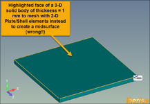
This is the command in FEMAP:
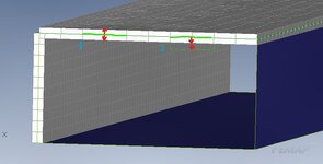
And this is the result: you see the nodes of the PLATE/SHELL elements are located in the top face of the 3-D Solid body ....
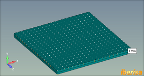
And if you activate the virtual thickness of the Plate/Shell elements (View Show Cross section command) the thickness of the plate element is the same of the solid body ... and if you do a PREVIEW ANALYSIS you will see the OFFSET applied in the NASTRAN inpuct deck: -0.5 mm (Offset from the surface of grid points to the element reference plane using ZOFFS parameter of the CQUAD4 command)
[
CODE]CQUAD4 1 1 1 2 81 80 -.5[/CODE]
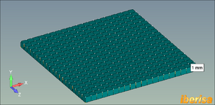
Yes, but activating OFFSET is a problem, you will have many, many limitations running different types of analysis with NASTRAN, see below:
- Offsets in the CBEAM, CTRIA3 and CQUAD4 elements are not allowed in combination with nonlinear material.
- The results in linear and nonlinear buckling with offsets may be incorrect.
- Simcenter Nastran doesn’t modify the mass properties of an offset element to reflect the existence of the offset when you use the ZOFFS or MID4 method. If you need the weight or mass properties of an offset element for your analysis, use the RBAR method to create the offset.
- ZOFFS should not be used when differential stiffness is calculated in solutions 105 and 200, and solutions 103, 107 - 112 using STATSUB, since the differential stiffness calculation does not include the offset vectors.
- ZOFFS should not be used in nonlinear solutions 106 and 129 in combination with thermal loads.
- ZOFFS is ignored for hyperelastic elements.
- ZOFFS should not be defined on elements which use MATS1 nonlinear material definitions.
- ZOFFS is ignored in heat transfer solutions 153 and 159 including any solution subcase which includes the case control ANALYSIS=HEAT.
In summary, my best recommendation is to run as always, using the classical method: create midsurfaces and use the mesh attribute option in the meshing paramenters SURFACE TO CENTERLINE, and you are done, OK?.
Best regards,
Blas.

