Continue to Site

Eng-Tips is the largest engineering community on the Internet

Intelligent Work Forums for Engineering Professionals

  • Congratulations KootK on being selected by the Eng-Tips community for having the most helpful posts in the forums last week. Way to Go!

Plate Uniform Moment Design 2

Status
Not open for further replies.

cgstrucg

Structural
Mar 21, 2018
135
Hello,

Can anyone please guide me on how to design the plate for the uniform moment shown in the attached sketch? I am following AISC for the design. It seems very simple design but I am getting a bit confused and wanted to be sure. Thank You for the help.

Thanks
 
 https://files.engineering.com/getfile.aspx?folder=0f8f2a3b-5e55-45ce-a134-802419594734&file=PXL_20211006_044748322.jpg
Replies continue below

Recommended for you

Plate's the easy part... use plastic moment modulus Z = t*d^2/4 (S for Aussies) and Mr = phi * Z * fy. The connections at the end with bolts may be a little trickier and the stability of the plate/connection may be an issue.

Rather than think climate change and the corona virus as science, think of it as the wrath of God. Feel any better?

-Dik
 
What is this connection for? My first impression when seeing it was, "No.... Just No. Don't do this."
 
I've done many connections like this, albeit not normally to another channel... generally welded on one end to some other structure... design method is the same...

Rather than think climate change and the corona virus as science, think of it as the wrath of God. Feel any better?

-Dik
 
Conceptually, isn't what you are trying to do the same as an extended single plate shear connection?

Are you actually trying to pass a moment from the top HSS section down to the lower one, or; are the top+bottom HSS connections a pinned; and you just have a moment in your connecting element?

There is an AISC article on extended shear plates if that helps. (see attached)

 
 https://files.engineering.com/getfile.aspx?folder=9c6ae74d-b814-4a6b-a94b-246c401f339b&file=Design_of_Unstiffened_Extended_Single_Plate_Shear_Connections.pdf
Yup... That's what I think... maybe really extended, and there could be other stability issues.

Rather than think climate change and the corona virus as science, think of it as the wrath of God. Feel any better?

-Dik
 
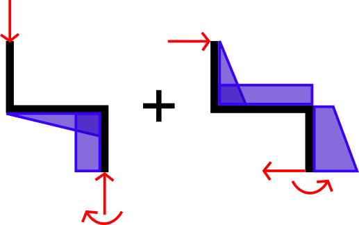
The moment in the plate is not uniform since the eccentricity from the vertical load changes along its length. Split up the applied loads and look at the moment diagram for each of them.
Plate_Moment_Diagram_bdpsq8.png

Your applied loads also produce moments in opposite directions. Is the horizontal load always to the right? Are there any load cases where one of the loads is not being applied? If so, then those load cases would control.

Structural Engineering Software: Structural Engineering Videos:
 
Hello,

Thank you all for the inputs. I should have mentioned the backstory. This connection is to support a curtain wall. This support would be on both ends of the curtain wall and I believe this would help make this connection stable. Is there any other concern you see? I am going to weld the bottom of the right HSS in this connection to a beam that is below it. The top of the left HSS in this connection is free.

Thanks
 
Is there a vertical load to be carried through the joint or is it just a flexural member carrying horizontal wind load from the curtainwall?

Must of the responses are geared toward some vertical component, like the thing is a hanger of sorts.
 
There is a very small dead load going thru the joints, as small as 1 kip.
 
See F11 in AISC for rectangular bars- may not apply if it's short enough.
 
Status
Not open for further replies.

Part and Inventory Search

Sponsor