Eng-Tips is the largest engineering community on the Internet

Intelligent Work Forums for Engineering Professionals

Plywood Gusset Design

TRAK.Structural

Structural
Dec 27, 2023
88
0
0
US
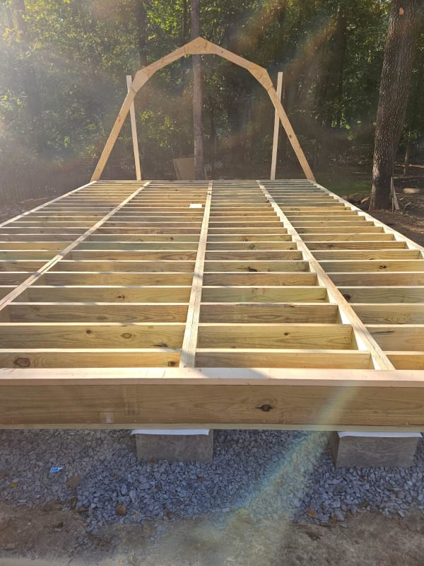
See image below. A local inspector has required an Engineer stamp on the framing that creates the roof/walls of this 16'x24' shed; so I have been called in on this. Analysis of the framing isn't too complicated but I am looking for some ideas on the simplest way to analyze the gusset/nails that connect the 2x members at the joints. Does anyone know of any guides/resources showing how the numbers are checked on this? For the nails, I'm thinking it could be as simple as checking shear on the nail group at each side of the joint based on taking the applied moment and dividing it by the distance between the centroid of each nail group?

unnamed_aoqfsv.jpg
 
Replies continue below

Recommended for you

OP said:
Does anyone know of any guides/resources showing how the numbers are checked on this?

I doubt such a thing exists with respect to joints transmitting moment.

OP said:
For the nails, I'm thinking it could be as simple as checking shear on the nail group at each side of the joint based on taking the applied moment and dividing it by the distance between the centroid of each nail group?

That sounds reasonable for strength so long as you're heeding edge distances etc. The trouble with the joints, in my opinion, is assessing their flexibility, which I would expect to be considerable. If the arch is on its own recognizance with regard to buckling or racking laterally under wind, this would give me pause.


Any chance this shed has a solid rear wall? If so, I'd be tempted to claim it as a three sided shear wall building laterally and take some of the heat off of these gusseted joints.


As you say I would just check the moment at the gusset joint and then do a nail group analysis for the moments, shears and axial forces to give you the worst case nail shear and check for that capacity. I suspect you will run into trouble with edge/end distances depending on how long the gussets are. How about designing them as glued joints then you are only restricted by the rolling shear of the ply gusset. Again you would need to do an analysis to get the max shear at the glueline.
 
Kootk - I kind of liken this to a prescriptive portal frame, where the nail pattern from the header to the sheathing resists some amount of moment. I haven't come across a detailed reference for how the portal frame was derived but was hopeful that something like this exists out there??

I may have to require 2x8 members to get any real moment resistance from a nail group considering the edge distance requirements in NDS, haven't run the numbers yet to even see how close or far off I think this idea is.

Blocking at a few places along the "arch" should take care of buckling.

Yes, the back wall will be solid which helps at the end of the structure, unfortunately the builder wants to do these "arches" across the entire length, 16" on center, so the common arches in the center wont get any benefit (for gravity loadings) from sheathing at the ends.

Phuduhudu - If I can get the numbers to work I would likely specify glue and nails as a belt and suspenders system. I've never used glue for the capacity checks, got any references on how one would check the glue as "structure"??

 
I would strongly avoid considering glue as the primary bonding element. How many discussions have occurred on this site regarding post install epoxy anchors, even with thorough instruction from the manufacturer with details on how to install. Imagine a framer trying to build a strong and continuous bondline in the field with wet plywood covered in dirt and plywood. Perhaps if clearly detail a clean bonding surface and a marine grade epoxy with sufficient application and clamping during curing.
 
It wouldn't be directly applicable to your situation, but the Timber Construction Manual has a chapter title "Moment Transfer" which briefly discusses moment connections between glulam pieces. It seems to be based on using steel plates and bolts (rather than plywood and nails).

Could you test a single frame as an alternative to analysis?
 
Eng1680 - Not sure that testing is something that I can pull off for a small residential shed, but I really do like the idea and being able to quantify real performance.

Just for fun, what would be your approach to trying to test something like this? Hanging weights from the frame, doing pullups on it, stacking sandbags on the roof after a few frames are built?
 
As long as you have a functioning shear resisting element at the front and back walls, you really only need the moment connection at the peak. The steeply slanted rafters are no different than wall studs where the roof diaphragm provides the stability. You could use a high collar tie in lieu of the gusset which would be easier to analyze albeit losing a little bit of peak headroom.
 
TRAK said:
Just for fun, what would be your approach to trying to test something like this?
Well, it was easy to write the comment, but thinking about it now, it does seem rather difficult. I think to get a meaningful result, you would need to construct 3 or 4 of the gusseted frames and then sheath them with plywood. I was originally thinking to just construct one, but it would obviously just buckle without sheathing.

I would probably want to load it to about 3 times the design roof load. I'm not sure how best to do that though.
 
Eng - Maybe I'll pitch the idea to the client, I'll take pics if it happens.

SW - Is it silly for a shed, sure, but I didn't pick this framing system. I'm just trying to detail it so that it is adequate.

Lex - [thumbsup]
 
Back
Top