Continue to Site

Eng-Tips is the largest engineering community on the Internet

Intelligent Work Forums for Engineering Professionals

  • Congratulations KootK on being selected by the Eng-Tips community for having the most helpful posts in the forums last week. Way to Go!

Portal Frame Nailing Patterns

Status
Not open for further replies.

medeek

Structural
Mar 16, 2013
1,104
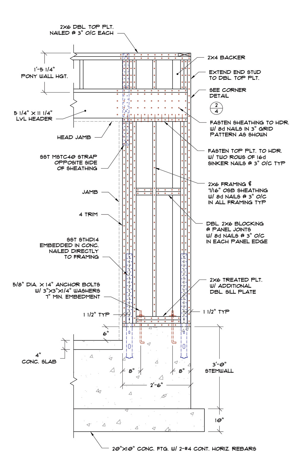
Due to the overwhelmingly positive feedback I received on my questions about the foundation/driveway question I thought I might post up one other item that has been bugging me for a while. I drew up this portal frame detail to show the nailing pattern per code so that a person with little or no construction experience could properly nail off the OSB so that it is structurally sound. However, with all those nails the whole thing looks like swiss cheese to me. Any ideas on the "correct" nailing pattern. I am trying to comply with the IRC 2012 nailing requirements for this type of portal frame.

GARAGE_DOOR_END_PANEL.jpg
 
Replies continue below

Recommended for you

I'm a ME but in the last couple of years I've dabbled in some garage and shed design, which I find much more interesting than a lot of the mechanical work that I do. Up until now I've spent a good bit of time utilizing the IRC to work through some of these designs however I still very much a "newbie". However, the IRC does have its limitations and I guess I need to start digging into the NDS and the ASCE 7 to really make sure all my designs are properly engineered. Any recommendations on what resources I should be consulting for the foundation (ie. spread footer for the concentrated loads at the garage doors). My first impression with the ACI is that it is geared more towards major reinforced concrete structures like bridges and high rises.

Everyone is more than welcome to take a look at the full planset I drew up here:


I'm sure there is plenty wrong with it as it is my first "real" planset that I've put out there. I've tried to make sure everything is compliant with the IRC 2012, so look at it through those lenses. Normally, most designers don't include full framing plans with their designs but my intent with this one was to provide a planset for the lowest common denominator, basically someone with zero framing or building experience.

What I really ought to do is pay to have a structural engineer go through the entire planset and run all the calcs and tell me what needs adjustment or fixing based on my basic design parameters.
 
medeek,

The footing is easy, if you just assume 1500 psf allowable brg pressure. You will come up with either A 30" square or 36" square depending on your exact gravity load there, don't include self-weight of footing (too conservative).

Make the footing 12" thick, bearing at depth dictated by your local Bldg Dept to get it below frost line (or 18" if you live in the desert), 3-#4 ea way for the 30" sq and 4-#4 ea way for the 36" sq.

Those rebar schemes are very common and I don't bother showing calcs for the rebar and concrete shear, no one else does, it seems (for residential).
 
Using only the IRC instead of actually designing a house by calculation is a PITA because you are always checking to see if you meet all the criteria for the IRC guidelines and load tables, and you are wondering what to do if there is for example a large concentrated load on a beam, etc.
 
You didn't ask this but I thought I'd comment anyway. I like having the pony wall hung from the beam rather than above it so that it doesn't form an unnecessary hinge.
 
I am a bit concerned with a mechanical engineer dabbling (as you said) in structural engineering. Even a single story residential structure can be a lot more complicated than the average person thinks, and there are plenty of SEs who may not know how to properly detail a portal frame.

You are in a pretty sketchy area as far as licensing is concerned and practicing outside your area of expertise.

If you have interest and the chops you should absolutely be learning under an experienced PE, and I would follow your own advice:
medeek said:
What I really ought to do is pay to have a structural engineer go through the entire planset and run all the calcs and tell me what needs adjustment or fixing based on my basic design parameters.
 
As far as the locals around here allow (PHX metro area), ANYONE can provide plans for a one-family private residence, as long as it follows IRC criteria and load tables.

It is up to the bldg. dept to determine if it needs gravity and/or lateral calcs by a licensed PE or SE. A licensed ME would not meet that criteria - it needs to be licensed PE in Civil Engineering or a Structural Engineer.

I imagine this is very common in all the USA states.

 
This planset is designed per IRC 2012. It is not engineered by myself or others yet. I am dabbling in architecture and residential design, not in structural engineering. I have never offered my services as a structural engineer or stamped any documents that involved structural engineering. I have stamped many documents involving mechanical stress analysis. However, that being said I have worked with a local structural engineer the last couple of years on some other projects and I have contracted with him to do all of the structural engineering for my plansets. My thinking is that even with a residential design it can't hurt to have someone else lay their eyes on it and pick out any problems. By law the requirements of the IRC usually suffice for many jurisdictions however as you suggest people are automatically suspicious of a (former) mechanical engineer doing residential and "structural" type work. The funny thing is that for the last year and half I have done far more residential design work than I care to admit but my degree will forever be "mechanical", unless of course I sit for and pass the SE exam in a couple of year, which may be a possibility.
 
The prescriptive lateral analysis for 1 and 2 story homes should be banned from the IRC in my opinion. Bunch of nonsense.
 
medeek

Check to see if Civil PE's can stamp low-rise structures in your state, or if there are any single-family house exclusions. That route may be easier for you.
 
I'm licensed in Utah and Washington and for both states you do not even have to be an architect or engineer to design residential structures. Utah in many cases requires that an engineer review and produce an analysis of the residential structure. However, that is between the customer and the building dept. to pursue. My objective is primarily to produce plansets that meet the requirements of the IRC and the basic minimum design parameters I am advertising them at.

Basic Wind Speed: 100 mph
Seismic: A,B,C,D0 (still looking at D1 and D2 to see if its worth the hassle)
Wind Exp.: C
Assume Flat Building Site
Roof Snow Load: 30 psf (Pf and not Pg)
Floor Loads: 40 psf
Stair Loads: 100 psf
Earth Pressure: 30 pcf
Soil Capacity: 1,500 psf

Ultimately, the local climate/geography/energy code will probably determine if the planset needs further engineering and modifications but that is beyond my scope.

However, after working with the IRC for a few months I find that some of its methods are either too restrictive or do not give enough direction. Hence, I have questions, that I have brought to this forum. As I mentioned above I have recently arranged for a full review of each planset by an experienced structural engineer since it will give me an education in residential structural engineering and also some piece of mind that I am not leaving anything to chance.
 
If an SE can't detail out a portal frame then he has no business being working as an SE in my opinion.
 
Just to complete the picture, here is the other side of the garage door shown above. Note that the second door also utilizes a portal frame:

GARAGE_DOOR_SEPARATOR1.jpg
 
medeek,

We helped you for some stuff but you can't really justify us checking everything. You initially overlooked the spot footing reqm't as I mentioned above, so be real careful.
 
In all fairness, every planset I have seen produced by our local non-licensed "residential designers" per the IRC has had serious deficiencies. I could go on and on about why nothing ever fell down but I won't.
 
The second detail has an approximate 70% overstress in the king stud (deflection not considered).

It also has way too many nails, hardware, and wood to make it desirable to build.
 
^^90 mph asce7-05 windspeed consideration... get closer to hurricane areas and the overstress goes up significantly.
 
It is only a 9' garage door, and I doubt the king studs are overstressed. Especially being 2x6 studs.

I corrected medeek regarding the nailing in my posts above.

This is based on a standard IRC detail that I also use frequently, so why are you so doubtful of it?
 
^^It's two (2) 9' openings in second detail. That is, at a minimum... 9' plus the 2' plus the trib. at the end. At least 12'+ trib in ordinary analysis of king stud.

please do the calc on 12' trib king stud at 90 mph.. 100mph, etc.

It's not just that... but how does the load really get to the king anyway? And if those straps take it (remember leeward is also a consideration) what is the bending, shear, deflection on providing face nails normal to wind?
 
Status
Not open for further replies.

Part and Inventory Search

Sponsor