Continue to Site

Eng-Tips is the largest engineering community on the Internet

Intelligent Work Forums for Engineering Professionals

  • Congratulations KootK on being selected by the Eng-Tips community for having the most helpful posts in the forums last week. Way to Go!

Position tolerance with axis as datum 1

Status
Not open for further replies.

MattEdwards

Mechanical
Mar 19, 2024
12
In this example, axis C is a tertiary datum for several other features, locating them in the left-right direction. If axis C is not perfectly perpendicular to datums A & B, this seems to create an ambiguous datum. Each end of axis C could be at a slightly different left-right position. How would this be handled during inspection? Is the centre point of axis C used as the datum?
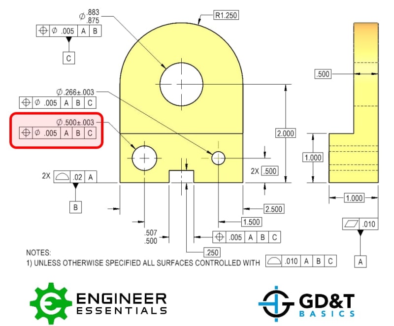
Figure3_brvedj.jpg
 
Replies continue below

Recommended for you

Datums are simulated by "datum feature simulators,"  which are essentially the components of the inspection fixture (or a virtual simulation performed by the software that analyzes the points generated by scanning the part). These simulators are required to be ideally related to each other. So any orientation error of the actual datum hole C won't impact the datum used for the establishment of the measurement reference.
 
And one extra comment: you have to qualify datum feature C position callout too Ø.005|A|B|. So, the circled hole location is to A|B|C| , but C is alredy qualified and into its positional tolerance.
 
The first two datums, A & B, orient the part and restrict the degrees of freedom except for the side-to-side translation. Since Datum C is being referenced at RFS you'd need to find the MMC virtual condition of that Datum C hole. Once you find that virtual condition hole center then you can check the position of the other holes.
 
MattEdwards,

The physical simulator for your datum[ ]C feature is a diamond[ ]pin. This makes contact on the opposite sides of your hole, defining your centre axis. The cut- away sides of the pin allow for your hole not being located perfectly.

--
JHG
 
drawoh said:
The physical simulator for your datum C feature is a diamond pin.
Not really. Could be a cylindrical pin. See Y14.43-2003 or 2011

Sliding Diamond Pin: This pin may be either diamond shaped, as shown, or cylindrical in shape.


pmarc calls it unnecessary distraction.........................


pmarc : I believe the cylindrical vs. diamond-shaped pin topic is an unnecessary distraction. The pin should always be cylindrical to match the Y14.5 theory. But the important part is that in the 2003 version of Y14.43 the pin C is sliding, whereas in the 2011 it is fixed at basic distance relative to the pin B (in order to make it sliding the translation modified would have to be applied for C on the drawing). This is basically a consequence of the change that was made from Y14.5M-1994 to Y14.5-2009 in the rules for mutual relationship between TGCs/datum feature simulators.
 
greenimi,

The diamond pin solves the problem of the hole not being located accurately in the vertical direction. There is no guarantee that an accurate round pin will enter the hole once the datum[ ]A and datum[ ]B features have been fixtured.

I don't know how seriously to take that drawing. You have a [⌀].005" positional tolerance being controlled by a fixture that picks up a hole [⌀].883/.875". You ought to specify datum[ ]C at MMC[ ]([Ⓜ]).

--
JHG
 
Drawoh,

That's why you make a cylindrical sliding pin and not a diamond pin
 
Plenty of assemblies use a slide to position an expanding pin as a tertiary locator. Not that I've ever seen one but there must be thousands of different examples somewhere.
 
Eric Gushiken said:
Since Datum C is being referenced at RFS you'd need to find the MMC virtual condition of that Datum C hole.

If datum C were referenced at MMB then that would be true. But at RMB (RFS), you'd need to have an expanding cylinder to find the axis desired.
 
Strictly per the Y14.5 definitions, the datum feature C simulator pin should be an expanding stationary cylinder. It shouldn't be sliding because a translation modifier wasn't used. It should be expanding because it was referenced RMB.
 
Thanks for all the replies, I understand now: it is the datum feature simulator used to locate the other features, and by definition the simulator is perpendicular to datum A.

If using a CMM rather than a gauge, presumably the CMM will create a the largest possible cylinder that is perpendicular to datum A and fits through hole C, and use the axis of that cylinder as datum simulator C?
 
Burunduk said:
Strictly per the Y14.5 definitions, the datum feature C simulator pin should be an expanding stationary cylinder. It shouldn't be sliding because a translation modifier wasn't used. It should be expanding because it was referenced RMB.

Burunduk,

Why are you assuming that 2009 is used?
This is happening when the OP does not provide enough info and he/she is not clear enough.

I assume 1994 is used.

I think you are 99.99% correct and 2009 or 2018 has been the intent of this training material. BUT again, without being specified everyone can do and assume everything they want.

 
Greenimi,
I assume Y14.5-2009 or 2018 is used because I recognize the source😉 but in principle, you are correct. From the question alone, not only it would not be possible to know which version of ASME Y14.5 is considered, but also whether it is ASME in the first place.

MattEdwards said:
If using a CMM rather than a gauge, presumably the CMM will create a the largest possible cylinder that is perpendicular to datum A and fits through hole C, and use the axis of that cylinder as datum simulator C?

More accurately, the CMM will create a cylinder located at the hole's true position (basic location) and ideally oriented relative to datums A and B, just large enough to fit through hole C. That cylinder would be datum feature simulator C and its axis datum axis C.

 
Just curious, which is more common in inspection departments? CMM's or articulated inspection arms? Also, what software is the most common? Verisurf? Is it easy to establish these datum sequences and conditions in the software?
 
Eric,
That's mostly depends on the company using the equipment. Generally smaller companies don't have large gauge rooms with dozens of specific machines. Larger companies and industry giants have multiple inspection rooms and expensive high end equipment.
My current company has 15 CMMs along with dozens of other measuring devices and my previous one had only a portable Keyence articulated arm. 1300 vs 80 personnel. Bigger size = more budget (mostly)
 
MattEdwards,

On a different note, you should consider |A|B|C⯈| as your DRF if you are using 2009 or 2018 version of the standard. This also usually indicates that the datum features are not "selected" correctly.
 
Status
Not open for further replies.

Part and Inventory Search

Sponsor