Sa-Ro
Mechanical
- Jul 15, 2019
- 279
Deal all
Kindly refer the attachment.
If position tolerance is applied with median plane datum for two holes, is it required to maintain symmetry between holes wrt datum median plane?
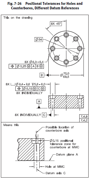
If counter bore and clearance hole is mentioned by hole callout, and positional tolerance with MMC condition. MMC will refer to counter bore or clearance hole?
Kindly clarify.
Kindly refer the attachment.
If position tolerance is applied with median plane datum for two holes, is it required to maintain symmetry between holes wrt datum median plane?
If counter bore and clearance hole is mentioned by hole callout, and positional tolerance with MMC condition. MMC will refer to counter bore or clearance hole?
Kindly clarify.