-
1
- #1
jonathan8388
Aerospace
Hi everybody. Long time lurker on these forums, but I think first time posting here. ASME Y14.5-2009 Senior.
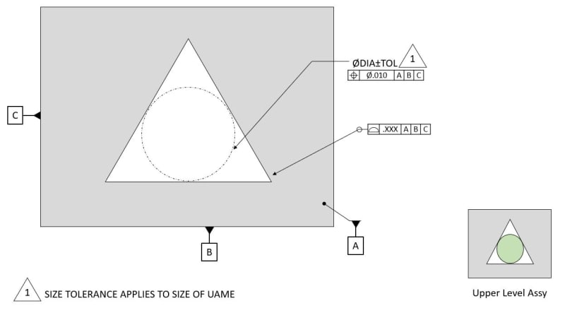
Have an interesting application for a part assembly fit that we are working on the tolerancing for. To break it down in a very simplistic state, the mechanics would be similar to a triangular shaped hole (ignoring corner radii) that would house a cylindrical part. The direct functionality that we would care about is the fit of this cylinder inside of the triangular cavity AND the positional error of the cylinder in the as-assembled state.
On the detailed triangle part, I would highly prefer to somehow control that functionality directly (tangent cylinder position) rather than the 3 walls with some profile and extrapolate out what an effect positional error would be. Obviously, I would need to control the entire profile of the triangle with some control, but for the ultimate part functionality, this tangent cylinder position is what I mostly care about.
One can argue that this could be an Irregular FOS type A, so my first off-the-cuff method here was to explicitly state that the UAME for this part is a largest-fit cylinder in the triangular cutout (so there is no different interpretation)and then position/size that UAME directly. Would have a note to state that the size tolerance requirement actually applies to the UAME contacting all 3 surfaces in lieu of an actual “feature size” which doesn’t explicitly exist here
Thoughts?
link to figure is below


![[banghead] [banghead] [banghead]](/data/assets/smilies/banghead.gif) , as I might not be able to understand it)
, as I might not be able to understand it) 
