Eng-Tips is the largest engineering community on the Internet

Intelligent Work Forums for Engineering Professionals

Positional Tolerance of Internal Triangle Tangent Cylinder 1

Status
Not open for further replies.

jonathan8388

Aerospace
Jul 31, 2015
20
0
0
US
Hi everybody. Long time lurker on these forums, but I think first time posting here. ASME Y14.5-2009 Senior.

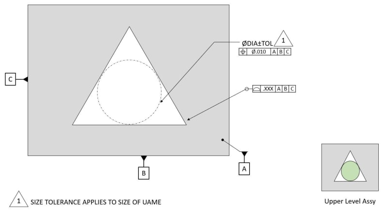
Have an interesting application for a part assembly fit that we are working on the tolerancing for. To break it down in a very simplistic state, the mechanics would be similar to a triangular shaped hole (ignoring corner radii) that would house a cylindrical part. The direct functionality that we would care about is the fit of this cylinder inside of the triangular cavity AND the positional error of the cylinder in the as-assembled state.

On the detailed triangle part, I would highly prefer to somehow control that functionality directly (tangent cylinder position) rather than the 3 walls with some profile and extrapolate out what an effect positional error would be. Obviously, I would need to control the entire profile of the triangle with some control, but for the ultimate part functionality, this tangent cylinder position is what I mostly care about.

One can argue that this could be an Irregular FOS type A, so my first off-the-cuff method here was to explicitly state that the UAME for this part is a largest-fit cylinder in the triangular cutout (so there is no different interpretation)and then position/size that UAME directly. Would have a note to state that the size tolerance requirement actually applies to the UAME contacting all 3 surfaces in lieu of an actual “feature size” which doesn’t explicitly exist here

Thoughts?

link to figure is below

 
Replies continue below

Recommended for you

I thought about that a little but and it is still a similar problem I think. I would ultimately be profiling the entire surface of the triangle back to the cylinder (datum target cylinder). If I were to profile the periphery of the profile tight, that would keep a tighter positional control back to the center cylinder but overly restrict the rest of the triangle that isn't so important. The inverse is true if I kept it loose. In that respect it is still and "indirect" positional requirement.

The point is that I care less about what the triangle does outside the tangent points at long a the 3 tangent points keep the center cylinder within a certain position. So the surfaces of the triangle AND angles can vary much more as long as the 3 tangents to the cylinder are well controlled (wherever they may be). Obviously there is also a size requirement of the cylinder going in there.

What I am showing I THINK should work, but the caveat is that I am directly forcing a specific UAME AND putting size requirements on it (not the feature itself since there really isnt a physical cylinder on the piece part to check size). This requires a note to clarify that.

I am just thinking of any "gotchas" with this. .
 
jonathan8388 said:
The point is that I care less about what the triangle does outside the tangent points at long a the 3 tangent points keep the center cylinder within a certain position. So the surfaces of the triangle AND angles can vary much more as long as the 3 tangents to the cylinder are well controlled (wherever they may be). Obviously there is also a size requirement of the cylinder going in there.

Sounds like a job for a nonuniform profile tolerance.
 
jonathan8388,
The method will work as far as the location of the cylindrical UAME goes.

However, you have to also make sure that the form of the triangle is controlled (for that I would use an all-around profile) and, if needed from the design standpoint, that the orientation of the triangle in the shown plane is controlled as well. Otherwise, the triangle may freely rotate about the UAME axis.
 
Also, if the size/shape may be controlled with the all-around profile, the UAME does not even have to have the size limits defined.
 
PMARC

Yeah I would put a loose all around profile to keep the triangle form somewhat defined from "running away". But I was thinking of still keeping the UAME size as-is to be more direct (unless that's an issue). That is more personal preference as its more direct to the geometry and function of the component going inside of it on the next higher assy.

That way the triangular surfaces have to conform to both specifications at the tangents (wherever they may be, which is the tighter more critical location) and the profile is a catch-all elsewhere.

Obviously there is no physical cylinder on the part to measure the dia, so thats where note 1 comes in.

Triangle2_m0vid6.jpg
 
Jonathan,
The all-around profile will already indirectly define some size limits for the diameter of the UAME. So if the specified size callout for the UAME diameter is going to define a looser size limits than the ones indirectly defined by the profile, the UAME size callout will be kind of redundant. If it is going to be otherwise, then you need to ask yourself if you really want to impose a tighter size requirement on the envelope diameter than would be indirectly controlled for free by the profile.

Also, you haven't specified which version of Y14.5 the drawing containing this feature is supposed to adhere to. If, by any chance, it is the 2018 version, then you may apply a dynamic profile modifier in the all-around profile FCF to let the profile requirement control form of the triangle only and make the UAME size callout indirectly control the size of the triangle.
 
Jonathan,
I did not notice that you edited your sketch while I was writing my reply.

The sketch you added confuses me a little bit because if the all-around profile references datums A, B and C, then it already fully controls the location of the triangle. Does it mean you want to control the location of the UAME in addition to the profile requirement?
 
Good question. Its the 2009 standard unfortunately, so the dynamic modifier was out.

The UAME size would be a tighter requirement than the profile. To me that makes the most sense as the general profile will keep things very loose for MOST of the triangle (that we care less about), but the tangents will be refined tighter to each-other via the UAME cylinder size AND position, which represents the mating component and interface. To me that gets right to to the functionality directly
 
PMARC sorry that we are crossing texts. Yeah I would have a large profile all around to all of the datums to loosely already control the form location and size of the triangle to keep it from "running away". Then at the tangents the triangle would be further refined via the UAME size and position (wherever they are located) and everything else will just "get out of the way" within the larger profile.

If the profile is large (which it should be) I would think this is ok since the surfaces just have to meet both specifications (as long as there is some overlap for a solution of both specifications simultaneously). Obviously that is up to me to make sure there is no conflict
 
ISO GPS has the concept of a "contacting feature". A geometric tolerance can be applied to a physical or imaginary gage, a pin or a sphere that contacts the considered feature of the part. There are certain geometries for which such controls are common, such as countersinks that can be gage-checked by balls used to determine the countersink's location, or tapered slots in which pins can be placed for similar purposes. Your idea is along the same lines. ASME Y14 standards, however, do not utilize such ideas. Nevertheless, the note you specified looks unambiguous enough.
 
Burunduk,
Since you brought it up, how the "contacting feature" works in ISO GPS. I contend that I am not familiar with that concept.
(Please, just explain it in the laymen terms, don't send me to the standard [banghead], as I might not be able to understand it)

Burunduk said:
ISO GPS has the concept of a "contacting feature". A geometric tolerance can be applied to a physical or imaginary gage, a pin or a sphere that contacts the considered feature of the part. There are certain geometries for which such controls are common, such as countersinks that can be gage-checked by balls used to determine the countersink's location, or tapered slots in which pins can be placed for similar purposes.

 
greenimi,
What specifically would you like me to clarify beyond the general idea of a "contacting feature" as I already described it (including simple examples) in the post you quoted?
 
Burunduk said:
What specifically would you like me to clarify beyond the general idea of a "contacting feature" as I already described it (including simple examples) in the post you quoted?

Basically, I would like to know what is the difference between using [CF] or not on the same application/feature?
I see some examples in ISO5459:2011 Annex E, but I am not able to fully understand what would be the outcome if [CF] is not used in those examples? Why do we need this modifier in ISO and what are the consequences of NOt using it (let's preted unintentionally).

Then, maybe to compare them with ASME's datum targent points or lines, how ASME is handeling the [CF] modifier?
 
greenimi,
The following figure is from ISO 10889 which is for "VDI" round shanks for tool holding. The parallelism tolerances do not apply to actual features of the part (the serration slots) but to pins used as "contacting features". The controls provide indirect indication about the orientation of the actual slots. It's not the same as applying tolerances to the actual part surfaces (for example, the form error does not affect the outcome - kind of like the tangent plane idea, but taken much further). I don't think there is a standardized equivalent to that in ASME.
Screenshot_20231110_192815_Drive_lylndl.jpg
 
Status
Not open for further replies.
Back
Top