Continue to Site

Eng-Tips is the largest engineering community on the Internet

Intelligent Work Forums for Engineering Professionals

  • Congratulations KootK on being selected by the Eng-Tips community for having the most helpful posts in the forums last week. Way to Go!

Positive moment connection

Status
Not open for further replies.

MIKE_311

Structural
Feb 15, 2020
108
I have a PS beam design where I am now designing the positive moment connection. The design calls for a significant amount of reinforcement at the pier diaphragm. The ends are going to be pretty congested. I could mix some hairpins with extending some of the prestressing steel but it's still a lot.

The other option is to specify the beams are at least 90 days before continuity is established to reduce the retraining moment from shrinkage.

How common is this? Any challenges to adding this requirement?

I know some DOTs have in their design standards that this is always the case, but this particular client (city but following DOT standards) doesn't indicate this nor do the discuss in the bridge standards.

Looking for any help or advice in dealing with this issue.
 
Replies continue below

Recommended for you

This is a simple span PC beam bridge made continuous for live load? I started to design a few of these several years ago, but decided it wasn't worth it and used link slabs over the piers instead. The pier diaphragms and positive moment connection made me shy away from it. How much capacity is gained by this type of design?

That doesn't help you very much with your problem though.

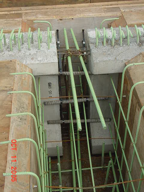
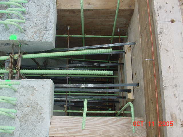
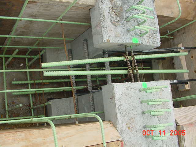
I will find some pictures of a bridge I was the inspector on when I was an EIT in Kansas. I have good pictures of the pier diaphragms formed up with all the steel tied. I don't remember there being that much steel in the pier diaphragms. Why are the pier diaphragms so congested?


MVC-066S_i3iy8l.jpg
MVC-064S_koqevu.jpg
MVC-065S_oxikuc.jpg
 
Positive moment would be in the span, but you seem to be talking about a connection at a support.
 
Hokie66 - Yes, this is the positive moment at the intermediate support due to patch loading. Not the usual positive moment resulting from a symmetrical load arrangement at mid span or thereabout.

Regards,
Qshake
[pipe]
Eng-Tips Forums:Real Solutions for Real Problems Really Quick.
 
Qshake,

"Patch loading" is a new term to me, but then I am not a bridge guy. Sorry for my ignorance, but traditionally, positive moment means the bottom is in tension. If the top is in tension, it is negative moment.
 
Rarely, there can be positive moment at the interior supports, due to upward camber of the girders resulting from creep. Upward camber (and net positive moment at the piers) is typically undesirable, and avoided by using harped or draped strands. The small amount of positive moment due to live load in another span is usually small enough that it doesn't overcome the negative moment from dead load.

Rod Smith, P.E., The artist formerly known as HotRod10
 
Hi Hokie66 - I'm sure there are other terms for this, and is not specific to bridge engineering, that is essentially loading continuous spans differently to produce different maximum results for shears, moments, reactions and deflections. Alternate span loading, skip loading are others I've heard over the years. I hope this makes more sense now.

Regards,
Qshake
[pipe]
Eng-Tips Forums:Real Solutions for Real Problems Really Quick.
 
BridgeSmith's explanation does make sense, but variation in gravity loading will not produce positive moment at supports.
 
Correct hokie66, the patch or skip loading is live load. We need to combine the lane load (uniform load) with vehicle wheel loads to produce maximum results for all responses.

Regards,
Qshake
[pipe]
Eng-Tips Forums:Real Solutions for Real Problems Really Quick.
 
Thanks for that, OSUCivlEng. Now I understand your comment above that "it wasn't worth it".
 
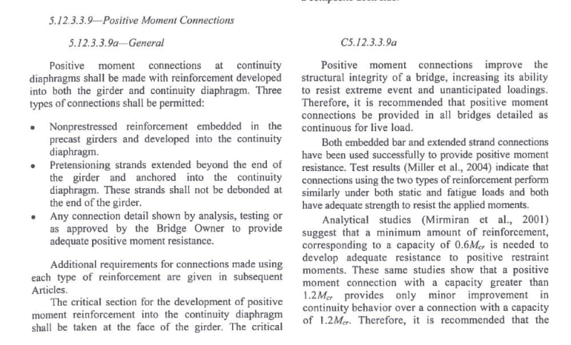
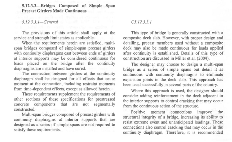
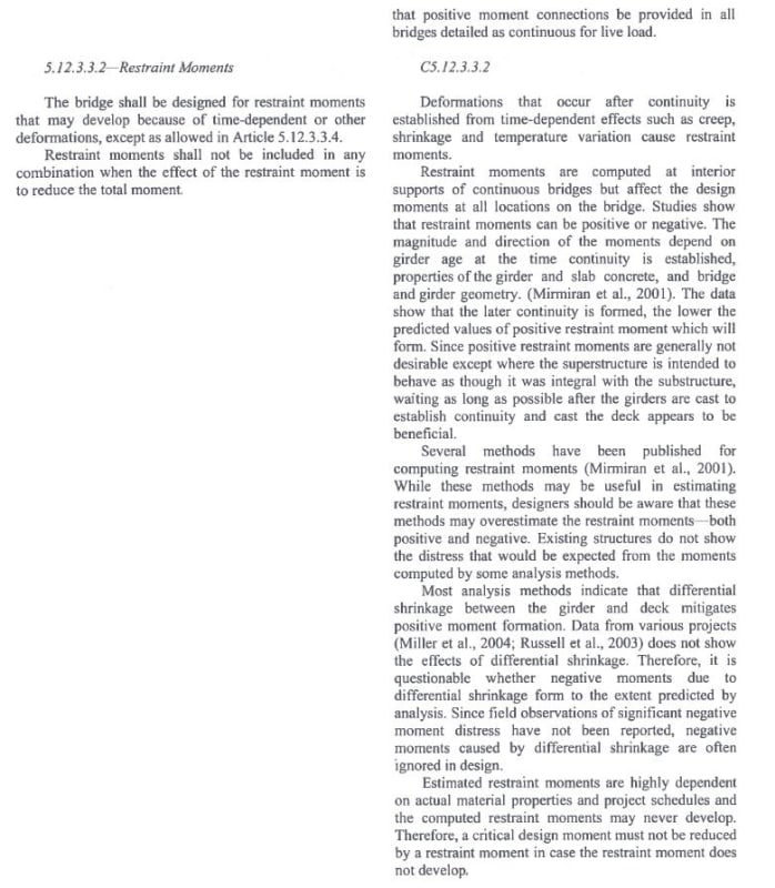
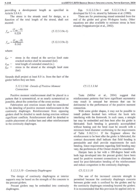
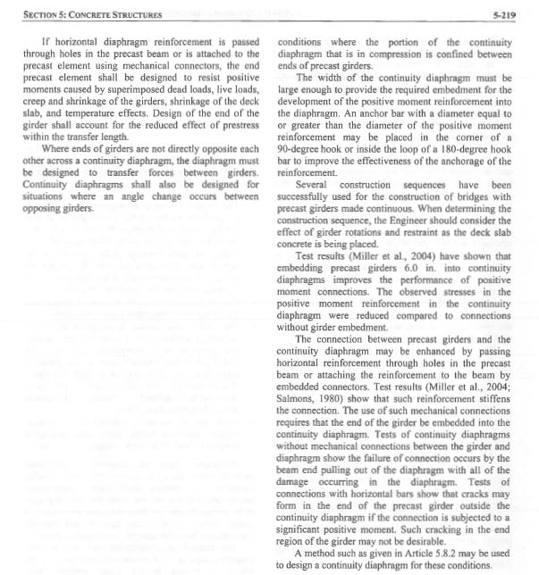
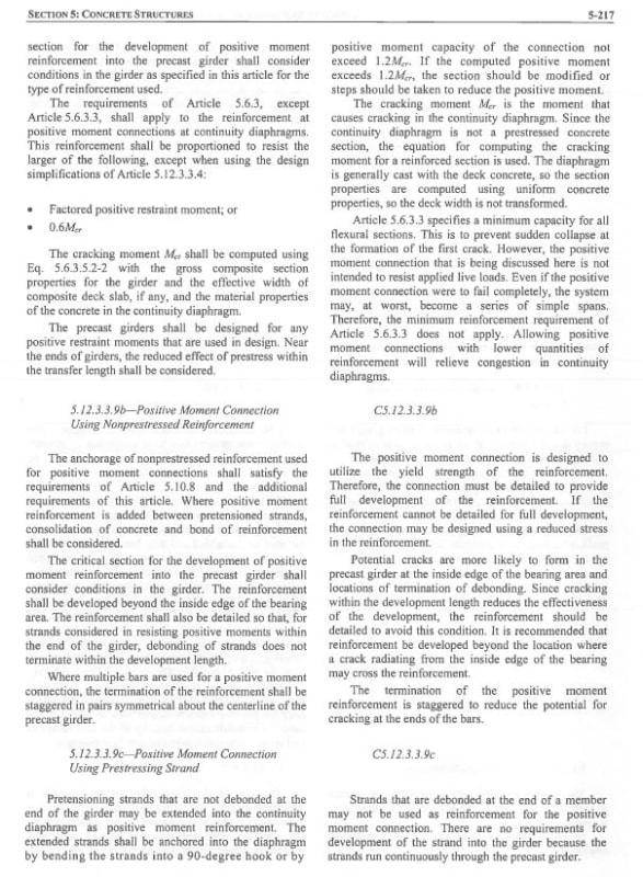
Thanks for the replies. Some background. This is indeed referencing the bridge response shown in AASHTO 5.12.3.3.9 above. This issue I was having is the moment generated at the supports due to differential creep and shrinkage between the beam and closure pour.

Turns out buried in the state's bridge standards, was a note to age the 90 days prior to pouring continuity diaphragms, this is what I was looking for- The difference between 28day and 90day in the creep and shrinkage calculations cuts the positive moment at the support by almost half.

 
How much capacity is gained from making a bridge continuous for live load?
 
Interesting question and one I never admittedly asked.

Without analyzing this bridge in particular. My bridge is a 3 span continuous. 60' ends spans, 75' main span.

If we look at 3 equal span and idealize the live load to a distributed load, a simple span max positive moment is 0.125wl^2. For a 3 equal span continuous, end spans loaded, the max positive moment is 0.101wl^2. So a ~20% increase by redistributing moment?

I don't know the history of this design, but my guess is that it stems from an effort to remove joints and since there is an increase in capacity you are allowed to consider it, provided its detailed correctly. It also likely helps manage compressive stresses in the beam from requiring more pre-stressing steel to carry all the live load. Although this design has some pretty shallow beams so, there is quite a bit of steel in the deck to carry the negative moment.


The dead load is still supported as a simple span, except for perhaps the rail. Live loads are point loads and not dead loads, so I'm not sure that's an apples to apples comparison. There is some gain in capacity, but I'm not sure if it's worth all the fuss.

If the desire is to remove joints in the deck, link slabs are a much simpler and less expensive way to go in my opinion. They are in the AASHTO Guide Spec for ABC, so I figure it's only a matter of time before they end up the Bridge Design Specs.
 
Relative settlement with respect to adjacent piers would also add to positive moment at a pier. Are you seeing these as well? If so, sometimes these can be reduced based on geotechnical studies. Depends on project specs and the DOT involved too I guess. Reduction of settlement effects can also be achieved by doing a time dependent analysis to see the effect of creep on moments caused at supports from settlement.
It is nice for DOTs to put guidelines to achieve "best behavior". If there is no tight time frame in the Contract of course.
 
Status
Not open for further replies.

Part and Inventory Search

Sponsor