Continue to Site

Eng-Tips is the largest engineering community on the Internet

Intelligent Work Forums for Engineering Professionals

  • Congratulations KootK on being selected by the Eng-Tips community for having the most helpful posts in the forums last week. Way to Go!

Post Drivers - Effects of Air Pressure, Mass and Springs on Impact

Status
Not open for further replies.

FoxLair

Agricultural
Jan 17, 2019
7
Full Disclosure - I am a building contractor with an affinity to design ways to reduce labor and/or allow me to complete tasks in an efficient way.

I have built permanent docks that utilize 4x4 treated posts driven into the lake bottom. Large pneumatic drivers work great but require an 80+ CFM compressor and a floating platform with a hoist of some sort to operate. On repairs. I have used a hand driver that is square metal tube with a cap and handles welded on. To automate this I added a Pneumatic cylinder to raise and lower this capped tube. It operates on a 5-6 CFM air compressor and works great.

Now the question: My goal is to drive a post with minimum blows while maintaining portability. I can add more mass, add springs or change pneumatic design. I understand how free falling mass and velocity affect impact. But, what makes my brain hurt is determining impact force when i add a pneumatic cylinder pushing downward at a specific PSI. Further brain strain is how adding a tension spring affects impact force (Given an extension spring constant (K), and a distance (d), how does this affect impact force of a falling mass)

What I can speculate is that either Air pressure or springs can increase velocity. I don't need exactness here, I just need to understand how I can better predict outcome and lessen trial and error time (of which I have invested a bunch).

Please help my poor brain in its hour of need.
 
Replies continue below

Recommended for you

You're gonna have to post some drawings, pictures, something. "I added a pneumantic cylinder" ain't much to go on. I can't imagine where you would be adding springs either.


I think I understand. I suggest you not consider springs because they only store energy and not increase it unless you have some kind of harmonics going on.
I'm picturing that you have something like a capstan operated drop hammer but using pneumatics in lieu of the capstan, and using the pneumatics for a downforce as well?
 
Have you looked at internal combustion pile drivers. or are these too big for your operation.
B.E.

You are judged not by what you know, but by what you can do.
 
You could also investigate vibratory pile drivers .
B.E.

You are judged not by what you know, but by what you can do.
 
You have three forces acting to move the hammer down. The weight of the hammer, the force of the spring, and the force of the pneumatic cylinder. Those forces acting through a distance, maybe d, generate a kinetic energy. Fsum * d = (1/2)* m * v * v
At impact the hammer has a velocity v. The momentum imparting a force on the pile is m * v. Impact force x time duration t of impact equals the momentum m * v. The mass of the pile and its resistance to being driven determines how far it will move at impact. The stickler is choosing the duration t of impact. 1 msec? 10 msec?

Ted
 
Go out and rent a PDA? At least you will get the facts, if not the theory. But that's what you're after, isn't it?
 
Assume plastic impact, the hammer stays in contact with the pile at impact.

The work done driving the pile is the driving force x the distance the pile moves, FD x D
The energy just as the hammer strikes is (1/2) x combined masses x velocity^2. The velocity is the velocity of the combined masses.
That energy works out to be (1/2)(mh^2 x vh^2)/(mh + mp) in terms of combined masses and hammer velocity at impact.
mh = mass of the hammer
mp = mass of the pile
vh = velocity of hammer mass at impact
FD = pile driving force, also ground resistance
D = distance the pile is driven after impact

The work done driving the pile = energy just after impact. The work done driving the pile is directly proportional to the square of the velocity of the hammer. The effect of increasing the hammer mass depends on its value compared to the mass of the pile.

Ted
 
Post_Driver_rymzlq.jpg

Thanks for the replies. I have looked into internal combustion drivers but I am not ready to abandon this project just yet.

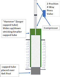
Above is a sketch of the driver. The current design is the same but no springs. It is portable enough to handle without a floating crane/hoist and works adequately, but slowly. Assume the "hammer" (tube and Cylinder) has a mass of 40#. I know from trial and error that increasing the mass to 120 pounds is ideal, but that is too heavy to handle without a hoist. The pneumatic cylinder has a 2" diameter piston with a 5/8 rod and 12" stroke operated @ 70psi. So my goal is to add 2 springs to give similar impact as adding 80# of mass. If my thinking is correct, if the mass is 1/3 (40 vs 120) then the new velocity needs to be the square root of (original velocity *3). Where my brain freezes is knowing if springs are capable and/or practical to approach the impact of a 120# hammer. Assume any increase in CFMs necessary will not be a limiting factor.

So, the challenge I face: with springs rated for a 12" extension, how do i determine what spring constant i need to achieve the approximate impact as would adding 80# mass? How does the stored energy at full extension affect velocity/impact potential of a falling object?
I have searched for a solution for so long that my wife says, "can you put that computer down for 5 seconds?" Please help my marriage

disclaimer: You likely only have to read a sentence or two to know my terminology and critical thinking are astray. Yet still I long for answers...
 
The work done by the spring would be (1/2)k(x2 - x1)^2, where x2 and x1 are final and initial spring positions. In your case x2-x1 = 12 inches. Equate the work done dropping 120 lbs. to the work done dropping 40 lbs. plus the spring work and solve for spring constant k.

Ted
 
Springs anchored to another sliding cap is a bad idea.
The springs will not be able to pull down on the hammer without pulling up equally hard on the second sliding cap. Assuming the second cap is much lower mass than your weight, they won't accelerate your hammer at all, they'll pull the light grey cap up off the post and your whole contraption will end up in the water.


The smaller tube is attached to the 4x4 post with a bolt on each side. Sorry it is not shown in the illustration. Even so, if the small tube/4x4 assembly has enough mass to keep it from raising off of the lake bottom at the start, will the upward pull on the post negate a portion of the impact force? In other words, would the springs need to be anchored to something other than the driver/post combo itself for maximum results?
 
ditto what I said earlier re the springs.
I seem to remember 120 pounds was the weight of the split spoon sampler driver that I had to carry around work sites. I agree not fun.
Are you using pressure to drive the piston down currently? The internet has instructions on building fast acting air valves from sprinkler valves. These are for air cannons but they may work to apply quick pressure to drive your piston down.
Or you could build in a valve to shoot in some starting ether and a spark lighter to set it off and drive a pile in one blow while you launch your driver into the air.
 
how do i determine what spring constant i need to achieve the approximate impact as would adding 80# mass?

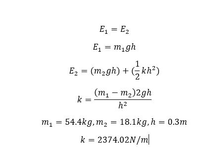
Assuming a perfect system (no losses, friction, 100% transfer of energy etc.), no damping effect from the cylinder as it out-strokes and your spring is set so it has 0 tension at the point of impact you can equate the total energy in each system.

For the first system (E1) energy is only the gravitational potential energy of the 120lb mass = m*g*h, where g is gravitational constant and h is height.

For the second system (E2) energy is the gravitational energy of the 50lb mass plus the energy stored in the spring =0.5*k*x^2, where k is the spring constant and x is the deflection (or in your case x = h).

Equate E1 = E2 and solve for k to find the spring constant needed (for 1 spring, divide by 2 for 2 springs etc.)

"Edit" sorry didn't realize you intended to use the pneumatic cylinder as well as the springs, have not accounted for that.

Capture_xpcblv.jpg
 
Some of this may be dependent on what is currently controlling or limiting your existing mass downward movement.
If your cylinder is always attached to the load, and the air cylinder is driving it downward, how fast does it end up moving at the bottom of the stroke? If the velocity at the bottom is currently less than what it would be under gravity free fall, then adding springs attached to the post may be just fine. It will just "help" your cylinder reach a higher velocity without pulling up the post. However, as I mentioned, if your velocity is currently being limited by fluid dynamics effects inside your pneumatic cylinder, the springs will not be able to add their full stored energy to the mass.

If your cylinder is already accelerating the load faster than 1g, then you're already exerting a net upward pull on the post during the downstroke. Adding springs will just make it pull upward more. Overall, anchoring the springs to a fixed point outside the post/driver system would be better.


"Or you could build in a valve to shoot in some starting ether and a spark lighter to set it off and drive a pile in one blow while you launch your driver into the air."

Love it. Of course the driver might also be in many separate pieces...
 
Wow! Tons of info here. Buggar, if I was only 15 again the ether suggestion would immediately rise to the top! However, due to lessons learned at the age of 15, I need to put that one on the back burner until I give up on the idea and want to destroy all evidence.

After considering the advice given and realizing that 4X4s float, I don't think I would have enough net mass with 2/3-3/4 of the length of 4x4 underwater. Although thinking outside of the box like Buggar, it may be a super charged water pogo stick.

Per Handleman's comment, The piston is currently adding acceleration. Using 100 Frame/Sec camera and slo-mo the average downward travel time goes from .25 sec in free fall to .19 sec. air assisted. I have 3/8" quick exhaust ports, which helps.

So, I think I will proceed with a combination of increased mass and developing higher/quicker air flow to the cylinder on downstroke of the hammer. Since springs will not be used, I may side mount 2 cylinders, one on each side rather than one on top. This will make it less top heavy and awkward and the second cylinder will add mass along with the addition of some steel attached low on the hammer. Then I can choke down air delivery with a ball valve at the start for easier guidance until the post gets 25-50% driven and then ramp it up as the imbedded post creates more resistance to upward pull. Where i need the most assistance is in the last 25% of depth.

Thanks to all for your feedback, and if you have more comments I am all ears. If you want to pursue Lake Pogo Stick fun, give me a jingle.
 
Buy an off the shelf air hammer and replace the tool bit with your rod and cap to drive the post.
 
Status
Not open for further replies.

Part and Inventory Search

Sponsor