Continue to Site

Eng-Tips is the largest engineering community on the Internet

Intelligent Work Forums for Engineering Professionals

  • Congratulations KootK on being selected by the Eng-Tips community for having the most helpful posts in the forums last week. Way to Go!

Post processing

Status
Not open for further replies.

T_M_S

Automotive
Dec 22, 2021
55
Happy new 2022 year :)
I would like to ask if it is possible to overlay FFT plots of 2 (or more) curves (plots) within one plot. I would like to compare one result with the other and being able to see FFT overlayed over each other with the same haxis/vaxis scale would be extremely helpful.

Thank you,
Ted

 
Replies continue below

Recommended for you

I assume you are using the ADAMS postprocessor?

The answer is yes it can be done.
pp_fft_nciw4p.jpg


Cheers

Greg Locock


New here? Try reading these, they might help FAQ731-376
 
Many thanks Greg.
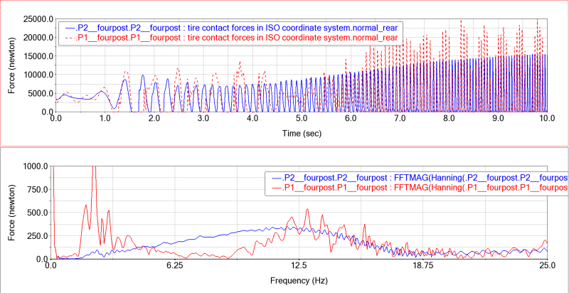
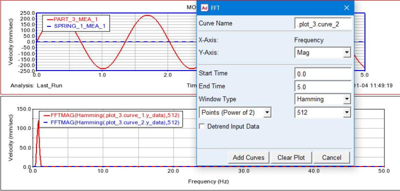
My problem is that I can't choose more than one curve in FFT window. I would right click it/browse and in browser window I can choose either curve_1 or curve_2. Trying to CTRL click them didn't help either. If I try to create FFT plots one by one - FFT on curve_1 and than another FFT on curve_2 then my curve_1 fft plot is gone and replaced by curve_2 FFT plot. I just can't figure out how I can avoid dleting replacing existing fft plot with another one or how can I choose more than one curve when I'm in FFT window.

In fact I did manage to have FFT of two curves on one plot but only when I started ADAMS today and imported results file and plotconfig file.
FFT_z8hbig.png

4post test rig/zero (~) damping vs damped amg_gt4

May I ask you to give me a hint on how I can have two FFT plots overlayed without this kind of workaround (importing results and plotconfig file).

Thank you,
Ted
 
I just changed the _1 to_2 in the dialog box. I don't actually use the postprocessor app, so I can't really explain any better. I export everything as req or whatever and use either hypergraph or matlab to crunch it.

Cheers

Greg Locock


New here? Try reading these, they might help FAQ731-376
 
Update: I kind of found a solution still but atill far from satisfactory. I can compare different analyses runs by saving a plot config file with pages/plots of interest. Then I import result files/plot config (add both results to plot config import window) - pages/plots are ready. But for some reason same curves are plotted/duplicated several times. It may be as bad as plot legend covering entire plot area. Deleting duplicate curves is current solution but it would be nice to avoid duplicating curves if possible.

I understand that my questions sound silly but I'm very new to ADAMS. I've always been around students that were playing with it and seeing how they struggle would scare me off. Now I decided to expand my understanding of race car/dampers dynamics. Reading some papers Kowalczyk, Alex Castrounis led me to start learning ADAMScar and Aride. In a week I created chassis, suspensions and full car assembly to closely represent the car I've worked with during season and have lots of logged data. Now I started learning simulating the car on 4 post rig and even more importantly post processing the results.

Main obstacles at this point is learning to choose appropriate input and most difficult task - actually understanding the results and learning to put into practice to gain performance on track.

Input.
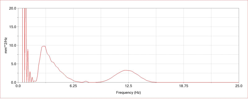
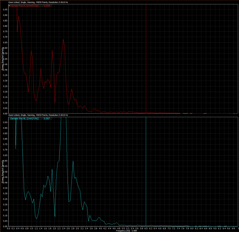
Kovalczyk in his SAE paper writes "First the downforce levels are determined for a given cornering scenario. Then the wheelpan input amplitude is varied until the power spectral density (PSD) of the damper displacement signals is similar to what is seen on the track." I thought that I will simply compare Motec/FFT PSD plots to Adams dal_ride_damper_data.displacement FFT PSD. I used -25/25mm sins weep from 0 to 20Hz and -10/10mm amplitude. but it turned out that numbers from Adams and Motec are very different.

FL_damper_D_fft_o1zora.jpg

APost dal_ride_damper_data.displacement FFT PSD -10/10mm displacement 0 to 20Hz

MotecFFT_ckaaov.png

Motec/I2 FL damper displacement FFT PSD

I'm confused and not sure if I'm comparing apples to apples. There's a feeling that may be software programs calculate FFT a bit differently and Motec data is like APost * 0.1 Any suggestions on the way to properly compare logged data/Aride data and developing a way to create representative input would be extremely helpful.

Thank you,
Ted
PS: Sorry for my self learned English.
 
Thanks for reply.
I posted my update before reading your reply, sorry. I tried doing it your way - changing _1 to _2 and it works but it deletes previous FFT plot. I looked in the preferences but didn't find anything that I could “tick off” to help with this issue.

Thank you for pointing me to think about external software for results crunching - I will look into it now.

Thank you,
Ted
 
The reason I use Matlab is that then I am in absolute control of how the FFT calculation is done. I don't like Car (but am now forced to use it), I don't like the Postprocessor (but at least I don't have to use it). I'm not surprised you saw students struggling with ADAMS, it is the wrong package with a 6 month learning curve. Frankly we had a graduates coming in and claimed he could use Car, the truth has been that with some handholding he did the tutorials at uni, and has now moved on.

I suggest you get up to speed on Fourier analysis, the best intro is and the best deeper dive is written by a Mr Randall who knows his stuff. In 30 years I have never needed anything more advanced on this for Fourier.

If Matlab is too expensive then GNU Octave works just fine if you can get it to read your data (I haven't checked that crucial fact), or you may be a Python person.


Cheers

Greg Locock


New here? Try reading these, they might help FAQ731-376
 
Thanks a lot Greg!

This links that you posted - many many thanks! Opened first link for a quick look – very concise and to the point text.
I understand that my questions regarding choosing proper input and sensible analyses of simulated data is digging into proprietary area but some times people will share a hint or two. I will post this questions in F1technical and see what comes out of it.

Thank you,
Ted
 
I read past what you are trying to do, way beyond what I get up to. DaveW would be the ideal contact but he hasn't posted for a couple of years.

Cheers

Greg Locock


New here? Try reading these, they might help FAQ731-376
 
Yeah! DaveW is the most knowledgable person in using frequency analyses/shaker rigs I ever seen posting on the web. I actually did try to contact him through pm on F1tech but as you said he didn't show up for plenty of time now.

Is he still working with Multimatic Europe? I'd love to get one of the cars that I work with on his rig.

Still I hope to get something out of this virtual Npost rig jorney. BTW, I assume that it is possible to add 3 more "posts" to existing 4post rig to convert it to 7post rig?t

Thank you,
Ted
 
Anything is possible, creating a new test rig is probably redundant, I'm sure someone has done it already, but I expect it is proprietary. If it as simple as holding the body at a known orientation while testing then that's easy to think about. Another option would be to switch aero on and effectively put your 4 poster in a windtunnel.

Cheers

Greg Locock


New here? Try reading these, they might help FAQ731-376
 
Wow! Now that is a great idea! But back to simulating physical 7/8 post rig. This is important in terms of validating the model if/when vehicle is tested on one.
“Holding the body at a known orientation” I assume that this is not the same as applying vertical force at prescribed chassis locations as done on physical 7post rig?
“Effectively putting your 4post into wing tunnel.” – this sounds great! I didn’t get to aero forces in Acar yet(I only saw that only drag forces are active in rigid chassis model). I assume that adding vertical forces is done in template builder… Checked it out and it is not obvious how do I create lift forces in addition to already present drag forces. Even less obvious how do I assign some sort of right height table to this downforce.
If/when I learn how to do aero forces (RH sensitive in particular) then it would very interesting. May be one can optimize for optimal pitch vs heave control compromise.

Thank you,
Ted
 
Have a look at file:///C:/Program%20Files/MSC.Software/Adams/2019_2_2/help/wwhelp/wwhimpl/js/html/wwhelp.htm#href=adams_car/forces.html

Cheers

Greg Locock


New here? Try reading these, they might help FAQ731-376
 
Thank you!
That's where I was looking when I told that it is not obvious :) Because it is defined in a bit of unusual way it will require some time to figure out. But I now I have to read through those Fourier link that you posted. I will get to aero in due time.

Thank you,
Ted
 
One side question. How does one edit .rpt property files manually (without using CurveManager)? For example I wanted to edit a road profile table file but when I open/edit/save it (as text file) and make sure that it has .rpt extension - still it is a text file rather than TeimOrbit file.
How do I save in TeimOrbit format? I was using Note.

Thank you,
Ted
 
Check what file extension it saved as. Typically text editors append .txt to the file name you thought you had, so you end up with flat.rpt.txt. Easiest way if ugliest is to rename the file after editing.

Cheers

Greg Locock


New here? Try reading these, they might help FAQ731-376
 
Thank you. My problem was that file extensions were hidden by windows. Had to tick it off to be able to truely rename the file (change extension)

There's one other side question. In 4post full vehicle analyses there's an option to use road profile tables as input. It can be a table with Y=road height and X = distance. If I choose input per wheel option than –
I thought that I can try simulating the race track surface (individual under each wheel) generated by ChassisSim bump profile utility. In ChassisSim own simulation it produces damper displacement signals very similar to those logged on actual car. It is interesting to see what happens if I use this “bump profile” as 4 post input.
Thank you,
Ted
 
Yes, that's exactly how I do primary ride analysis - we had our ride surfaces scanned and then drive the ADAMS model via the 4 poster, and compare it with a car driven over the same tracks. To complete the game we should put the test car on the real 4 poster and drive it with the same files. One day when I've got time...

Cheers

Greg Locock


New here? Try reading these, they might help FAQ731-376
 
Thanks.
Good to know that this is a tried and proven method. I understand that it hasn’t been validated on 4 poster but did you see correlation with data logged from physical vehicle? Did virtual rig findings transfer well to real car?
What was the sampling ratio/triangle size of the road mesh that you used? By default ChassisSim’s resolution is low:

[ROAD_PROFILE]
(XY_DATA)
{station <m> elevation <length>}
0.00 2.2
0.99 0.7
1.98 1.7
2 .98 0.6
3.97 1.6
4.96 1.0
5.96 1.2
6.95 2.7
7.95 1.9
8.95 1.5
9.94 -0.1
10.94 0.7
11.94 -0.3
12.95 0.6
13.95 -0.4
14.95 0.6
15.96 -0.2

I suspect that this may be too low resolution that may lead to erroneous results. I will have to check if ChassisSim can produce a higher sampling frequency.

The most troubling so far is that Aride only offers constant velocity (4post with road profiles) where I would like to simply submit speed vs distance table – same way that I did for road profile. I’m sure that experienced ADAMS user can do it but with 2 weeks Acar newbie this is something beyond my current abilities.
What I can do now is looking at short sections where constant speed is still representative. For example I could look at critical areas on track where bumps, curbes etc are strongly effecting the car/driver and lap time.

Thank you,
Ted

 
What you could do is fudge the x values by your true velocity /adams velocity, after all you are feeding the 4 poster a time history in reality.

Our standard ride roads are scanned at 6mm grid intervals because one day we hope to get up to 30 Hz, even so that seems excessive, 40mm should be enough.

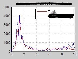
The correlation can be very good, for instance here's an overlay of the fft of real data from the track and ADAMS, for vertical vibration

pr_corr_zbil22.jpg


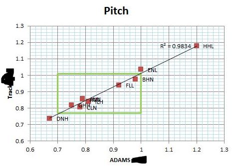
and here's the results of testing for pitch for one vehicle in many configurations (basically a swing on damper settings at each end). These are the RMS values for a filtered spectrum-all ride work is filtered for analysis.

pr-corr-2_cx0xw5.jpg


Bear in mind getting correlation like this initially took two of us (one on the car, me on ADAMS) several weeks, at least for me.

Cheers

Greg Locock


New here? Try reading these, they might help FAQ731-376
 
Status
Not open for further replies.

Part and Inventory Search

Sponsor