Continue to Site

Eng-Tips is the largest engineering community on the Internet

Intelligent Work Forums for Engineering Professionals

  • Congratulations KootK on being selected by the Eng-Tips community for having the most helpful posts in the forums last week. Way to Go!

Post processing

Status
Not open for further replies.

T_M_S

Automotive
Dec 22, 2021
55
Happy new 2022 year :)
I would like to ask if it is possible to overlay FFT plots of 2 (or more) curves (plots) within one plot. I would like to compare one result with the other and being able to see FFT overlayed over each other with the same haxis/vaxis scale would be extremely helpful.

Thank you,
Ted

 
Replies continue below

Recommended for you

Thanks!

Your results look very impressive.

One thing: “What you could do is fudge the x values by your true velocity /adams velocity, after all you are feeding the 4 poster a time history in reality.”
May I kindly ask you to get into more details here? I’m not sure I can fallow you.

Thank you,
Ted
 
If you are at 36 kph then you are travelling at 10000 mm/s, so a 100 mm grid is the same as a time history at 100 Hz, if you double the speed then it is 200 Hz, so you could change the grid spacing to 50mm and continue at 36 kph.

So if you were acclerating from 36 to 72 in real life, you'd start with a x grid spacing of 100 and end on 50.


Cheers

Greg Locock


New here? Try reading these, they might help FAQ731-376
 
Thank you,
But anyway - I assume that comparing to 40mm that you suggested as enough (not even mentioning 6mm that you actually run) that huge grid spacing that ChassisSim produces is useless? I need much higher resolution and other than scanning there's no way I can get there?

Then it is back to sine input and more reading on how to select a proper input based on logged data. Anyway, I’m not even ready for proper sine wave. Everyone seem to use a sine sweep with fixed maximum input speed of 100mm/s. How is it possible to achieve it in Aride?

Thank you,
Ted
 
Unfortunately this is the point at which your limited experience with Car exceeds mine, not that I do much ride work any more, we have a different, proprietary, way of doing it which seems to work very nicely and the non-ADAMS using development engineers tend to use it directly. AFAIK Car doesn't have a 4 poster test which seems a bit rude.

Ride has a getting started manual, with a swept sine file:///C:/Program%20Files/MSC.Software/Adams/2019_2_2/help/getting_started_carride/wwhelp/wwhimpl/js/html/wwhelp.htm#href=2_four_post_tutorial.2.4.html

It is usually possible to generate the input files by using matlab scripts or spreadsheets. In your case you might think about going to a time based input waveform. Writing rsp files is a bit of a pain, they are also known as RPC III files, I think I used to use Hyperworks to write them, a long time ago.

Cheers

Greg Locock


New here? Try reading these, they might help FAQ731-376
 
Thanks Greg,
It was a case of me not paying attention well enough. In Acar there's a choice of rig pad inputs - displacement/force/acceleration and velocity where I can assign velocity amplitude. Works well.
May I ask about the way and format you export data for postprocessing. You mentioned Matlab and Hyperworks/hypergraph as primary tools that you use.
Somehow I always avoided learning matlab. Know nothing about writing codes/programming and Matlab looked like it is exactly that. I also knew that one day I will have to :) We do have hyperworks on a couple of computers here and I’m a little familiar with it and first I started this virtual 4/7post rig exploration in hypermotion. My problem with hyperworks was that if I would assembly the full car model on a rig and simulate static equilibrium on 7post (0 motion) than my “corner loads” would change from run to run without me changing anything on the car. More than that – total car weight would change 2 to 31kg! – again I wasn’t changing the model, after I noticed it I was just repeating runs to see what’s going on with corner loads. After that I thought that I can’t trust what I do with HyperMotion and moved to ADAMS :)
Still curious what was wrong with me or hypermotion.

Thank you,
Ted

 
There's one more question. (They never seem to end):
When performing SVC simulation I get front and rear ride heights. I was searching hard but could not find HP, Marker or CFR it is tied to. How can I find coordinates of this front/reae RH points?

If you find time to answer in which way/format you export files to matlab it would also be great.

Thank you,
Ted
 
Hyperworks - I never got the MBD side of it to work, I mostly (99%) just use hypergraph for plotting. Occasionally I might dabble in hypermesh and optistruct but with no great enthusiasm.

ADAMS output to Matlab. I have not tried it, and don't know what sort of files it is expecting. I export req files and use a proprietary Req2Cdf converter that turns them into a data format that our proprietary matlab toolbox uses. There used to be a publically available set of file translation scripts, I have had no luck finding them today. other options would be .res or .rsp files, the latter are actually RPC III which is a data format often used in data acquisition.


Cheers

Greg Locock


New here? Try reading these, they might help FAQ731-376
 
Many many thanks!

Can you help with this one? When performing SVC simulation I get front and rear ride heights. I was searching hard but could not find HP, Marker or CFR it is tied to. How can I find coordinates of this front/reae RH points?

Thank you,
Ted
 
The ride heights are relative to the hardpoints you put in. So if you put in all your hard points at say curb , but run svc at 2 up, the wheels move up relative to the body, and for some reason svc reports that as a negative value. I think it use the wheel centre marker, for this, check the adm if you really want to know.

The main use of this is to allow you to set your spring preloads up so that the vehicle rides at the correct height. Another way is to run SPMM and look at the wheel force curves but that takes forever in comparison.

Cheers

Greg Locock


New here? Try reading these, they might help FAQ731-376
 
Thanks. I understand that but I can't figure out which exactly point (and its coordinates) is used in TR car in shared directory which I used as a base for my model. To know if my model is setup at design height I have to know this ride heights are measured on the chassis part...Can't fined it.

"The ride heights are relative to the hardpoints you put in. " I didn't put them but I wish to know how to find where ADAMS did. I would preder to move it to actual points used when setting the car up on the scale pads.

"check the adm if you really want to know." - would you please explain what does it mean? What is adm?

Thank you,
Ted
 
I found adm file in results folder.

!Front left ride height 1 marker ID
!Front left ride height 2 / stad tire reference marker ID
!Front right ride height 1 marker ID
!Front right ride height 2 / stad tire reference marker ID

Above is what I found for ride height but this doesn't help me identify actual marker/entity that defines coordinates.

Thank you,
Ted
 
If you look in your working directory there is a .adm file for each test you have run. This is full of Solver language (the guts of ADAMS) defining your model, exactly.

In it there are requests like these

REQUEST/5023
, DISPLACEMENT
, I = 1474
, J = 2457
, COMMENT = LEFT REAR SPINDLE RISE
, RESULTS_NAME = spindle_rise_lr
!
! adams_view_name='testrig.spindle_rise_rr'
REQUEST/5024
, DISPLACEMENT
, I = 1499
, J = 2458
, COMMENT = RIGHT REAR SPINDLE RISE
, RESULTS_NAME = spindle_rise_rr
!
! adams_view_name='testrig.spindle_rise_lf'
REQUEST/5109
, DISPLACEMENT
, I = 348
, J = 2455
, COMMENT = LEFT FRONT SPINDLE RISE
, RESULTS_NAME = spindle_rise_lf
!
! adams_view_name='testrig.spindle_rise_rf'
REQUEST/5110
, DISPLACEMENT
, I = 365
, J = 2456
, COMMENT = RIGHT FRONT SPINDLE RISE
, RESULTS_NAME = spindle_rise_rf

The i and j numbers are markers which are attached to parts

MARKER/348
, PART = 25
, REULER = 180D, 90D, 0D

is attached to

! adams_view_name='GL11a_V457_a10_fst.gel_hub'
PART/25
, QG = 1585, -810, 531
, MASS = 0.01
, CM = 334
, IM = 335
, IP = 1, 1, 1

The hub bearing, which located at the wheel centre hardpoint.

The j marker is

! adams_view_name='mal_wc_marker_on_body_front'
MARKER/2455
, PART = 234
, QP = 1585, -810, 531

attached to the body part
! adams_view_name='GL11a_V457_btt.ges_body'
PART/234
, MASS = ...
, CM = 2393
, IM = 2394
, IP = ...

at the same location.

So the request is measuring the displacement of the marker( in x y z) on the wheel relative to a marker which starts at the same location but is fixed to the body.

At the end of the adm there is often a table of all the hardpoints, which are read in from the hardpoint table in your sub assemblies in Car.

wheel_center left/right 1585.0 -810.0 531.0

Cheers

Greg Locock


New here? Try reading these, they might help FAQ731-376


Thanks a lot for your time Greg.
Here’s what I found in my adm (request numbers are obviously different than yours):

REQUEST/650
, DISPLACEMENT
, I = 804
, J = 1214
, COMMENT = LEFT FRONT SPINDLE RISE
, RESULTS_NAME = spindle_rise_lf
!
! adams_view_name='testrig.spindle_rise_rf'
REQUEST/651
, DISPLACEMENT
, I = 830
, J = 1215
, COMMENT = RIGHT FRONT SPINDLE RISE
, RESULTS_NAME = spindle_rise_rf
!
! adams_view_name='testrig.spindle_rise_lr'
REQUEST/652
, DISPLACEMENT
, I = 445
, J = 1216
, COMMENT = LEFT REAR SPINDLE RISE
, RESULTS_NAME = spindle_rise_lr
!
! adams_view_name='testrig.spindle_rise_rr'
REQUEST/653
, DISPLACEMENT
, I = 476
, J = 1217
, COMMENT = RIGHT REAR SPINDLE RISE
, RESULTS_NAME = spindle_rise_rr

I’ll trace request/ 650

I marker

MARKER/804
, PART = 95
, REULER = 180D, 90.5D, 0D
!
! adams_view_name='revref_1'

Attached to
1.gel_upright'
PART/95
, QG = 0, -824.17, 317.68
, MASS = 1.397298275
, CM = 785
, IM = 790
, IP
J marker
adams_view_name='mal_wc_marker_on_body_front'
MARKER/1214
, PART = 134
, QP = 0, -824.17, 317.68

Attached to

adams_view_name='GT_4_Body_1.ges_chassis'
PART/134
, MASS = 850
, CM = 1074
, IM = 1101
, IP = 2.204453E+08, 1.067216E+09, 1.181078E+09

But I think that this is not request used in SVC ride height measurements:


Wheel hop natural freq. Hz 18.67 18.67 18.67
Wheel tramp natural freq. Hz N/A
Front ride frequency Hz 2.35
Front ride height mm 189.48 189.11 189.85

Adams Model Title:
<private>/assemblies.tbl/GT4_3.asy


REAR SUSPENSION CHARACTERISTICS

Suspension Description: <private>/subsystems.tbl/GT4_Rear_v2.sub
_________________________________________________________________________

(PARAMETER) (UNITS) (AVERAGE) (LEFT) (RIGHT)
_________________________________________________________________________

Unsprung mass (total) kg 50.00
Unsprung c.g. height mm 328.25

I think that this “Front ride height” is taken from this request:

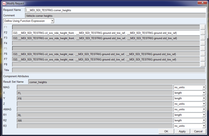
adams_view_name='testrig.corner_heights'
REQUEST/484
, COMMENT = Vehicle corner heights
, CUNITS = "no_units", "length", "length", "no_units", "no_units", "length"
, "length", "no_units"
, CNAMES = "", "FL", "FR", "", "", "RL", "RR", ""
, RESULTS_NAME = corner_heights
, F2 = DZ(763, 1224, 1224), F3 = DZ(782, 1224, 1224), F6 = DZ(409, 1224, 1224), F7 = DZ(423, 1224, 1224)

So now I have to trace

Markers 1224 and 763, 782, 409, 423

adams_view_name='testrig_std_tire_ref'
MARKER/1224
, PART = 1
, QP = 0, 0, -1.787586919

Attached to

PART/1
, GROUND

And corresponding marker

adams_view_name='coomarker_1'
MARKER/763
, PART = 93
, QP = 41.74107526, -65.40662309, 177.1452993
, REULER = 358.7416187D, 87.53720377D, 187.5375318D

Attached to

adams_view_name='AMG_GT4_Front_v1_1.gel_lower_control_arm'
PART/93
, QG = 37.26666667, -531.6066667, 126.9633333
, REULER = 352.4624682D, 87.53720377D, 181.2583813D
, MASS = 1.611395494
, CM = 747
, IM = 752
, IP = 15081.03519, 35508.4425, 20678.60294

Now that was unexpected….

Rear:

adams_view_name='coomarker_1'
MARKER/409
, PART = 58
, QP = -11.24411028, -74.77398238, 120.8819237
, REULER = 5.153076432D, 86.53837824D, 167.9936689D

Attached to

adams_view_name='GT4_Rear_v2.gel_lower_control_arm'
PART/58
, QG = 2665.6, -538.8433333, 188.9833333
, REULER = 12.00633107D, 86.53837824D, 174.8469236D
, MASS = 6.557425487
, CM = 398
, IM = 401
, IP = 71240.6575, 1.716880578E+05, 1.019588854E+05, 0, -14438.81923, 0

OK. Then I traced on of this LCA markers in template builder/double wishbone

Object Name : ._double_wishbone.gel_lower_control_arm.coomarker_1
Object Type : Marker
Parent Type : Part
Adams ID : 0
Active : NO_OPINION
Local :
Location : -102.6179846913, -79.5043512717, 104.8080076037 (mm, mm, mm)
(LOC_RELATIVE_TO({0, 0, 0}, ._double_wishbone.ground.cfl_lwr_strut_loc))
Orientation : 358.1514816192, 99.1762033404, 180.0 (deg)
(ORI_RELATIVE_TO({0, 0, 0}, ._double_wishbone.ground.cfl_lwr_strut_loc))
Global :
Location : 100.0, -650.0, 200.0 (mm, mm, mm)
Orientation : 0.0, 0.0, 0.0 (deg)

At list now I know where it is on template level. It turns out that it is located at the same coordinates as hpl_lwr_strut_mount.

OK, now some more digging required to locate that 'testrig_std_tire_ref'

To be continued :)

Thank you,
Ted

 
At this point while trying to learn/understand how this SVC ride height thingy works and to be able to modify it to suit my needs (I want it to measure Dz from user defined chassis points to ground) but I'm lost.
I found this request
RideHeighjtRequest_izrsxo.png


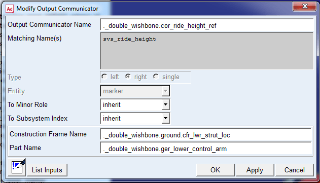
I think that I found it on template level (_double_wishbone.tpl)

_ride_height_ref_bb269z.png


At this point I wanted to look at __MDI__SDI_TESTRIG to see what’s inside of it. Funny thing is that I just can’t find it databases. Do you know where it is located?

I understand that anything is possible. I also understand that this is a bit too much to ask but I will give it a try.

Is this possible to do it (modifying SVC so it shows FR/FL/RL/RR ride heights at my own chassis locations)?

I would guess that for this I have to:

1.Create markers at desired chassis locations.

2. Create Output Communicator on chassis template. Similar to 2nd screenshot.

3. Modify request .__MDI_SDI_TESTRIG.corner_heights so that it uses my markers.

Problem is that to be on the safe side I would like to keep original __MDI_SDI_Testrig unchanged and substitute it with my own version.

Also I can’t figure out which file is representing SVC procedure and where to find it. Looking in A/car database didn’t help. I wanted to look at the file to see what’s inside and if I can edit it.

I did manage to create my own requests measuring distance from ground origo to my chassis points and I can plot them after simulation but I wanted to have it included in SVC if at all possible.

Thank you,
Ted
 
MDI TEST RIG seems to be hidden somewhere, there's no file of that name.

I see no reason to mess with the testrig template to do that, you can just as easily (ha) modify your instrumentation template, I think.

There's a whole bunch of requests called things like adams_view_name='testrig.svc_output_2' which may be what it uses in the reports.

I can't find where svc is defined, I know where it is in /Chassis but /Car uses a different file structure. In chassis it is a python file.

Cheers

Greg Locock


New here? Try reading these, they might help FAQ731-376
 
Hmmm...Can I do the same things (in terms of 4 post) in /Chassis that I can do in Acar? Just looking at the /chassis database it seems to have more useful things in there.

I would love to have a bit more freedom... Like having my own SVC utility that will output the things I want in a way that I want it. Like showing ride heights my way. May be even display not just corner weights but also calculate cross/wedge %, left $, Rear % for instance?

Also was dreaming to be able to modify template so that camber/toe changes are done the way it is done on the car that I work with. For example, changing toe by altering Tie rod length. Or shimming (moving outboard) lower control arm chassis points to alter camber. With one car a camber change requires toe resetting, spring preload resetting to get the car to baseline trim with new camber angle. Another car toe is altered via shimming tierod length and camber by shimming steering arm on upright…

May be while I'm at such an early stage I should switch to /Chassis? I guess that there's a reason that you use chassis (even if it's completely modified) instead of Acar?

In the meantime I settled with postprocessing software. Simcenter Testlab is very good with plotting and it reads RPC3 files.

Thank you,
Ted
 
We're switching from /chassis to /car for reasons that have never been entirely clear, and i believe that MSC will cease to support /chassis once we abandon it (maybe you could check with them). If they are going to support it down the track then yes, it is a lot easier to customise. For a start the marker ids are fixed, so you can write little bits of code like this, which is magically generated in excel:

********************************
* *
* FRONT SIMPLE STABILIZER BAR *
* Greg Locock v1.1 for GL9h3 *
********************************


MARKER/110465,PART=102 LEFT FRONT STABILIZER LINK TO ext
, QP=1660.00,-630.00,477.00
, ZP=1629.00,-629.00,601.00

MARKER/110566,PART=103 RIGHT FRONT STABILIZER LINK TO ext
, QP=1660.00,630.00,477.00
, ZP=1629.00,629.00,601.00

MARKER/114961,PART=149 LEFT FRONT STABILIZER BAR TO ext
, QP=1907.00,-339.00,469.00
, ZP=1907.00,339.00,469.00

MARKER/114962,PART=149 RIGHT FRONT STABILIZER BAR TO frame
, QP=1907.00,339.00,469.00
, ZP=1907.00,-339.00,469.00

adams_view_name='gel_Stabilizer_Bar_FRONT'

PART/132,CM=13200,MASS= 1.47,IP=6.4600e+04,7.3700e+01,6.4600e+04
, 0.0000e+00,0.0000e+00,0.0000e+00
M/13200,QP=1907.00,-314.50,469.00
M/13250,QP=1907.00,0.00,469.00
, ZP=1907.00,-339.00,469.00
M/13261,QP=1907.00,-339.00,469.00
, ZP=1907.00,339.00,469.00
M/13263,QP=1629.00,-629.00,601.00
M/13211,QP=1907.00,0.00,469.00
, ZP=1907.00,-339.00,469.00
M/13210,QP=1907.00,-629.00,469.00
, ZP=1629.00,-629.00,601.00

adams_view_name='ger_Stabilizer_Bar_FRONT'

PART/133,CM=13300,MASS= 1.47,IP=6.4600e+04,7.3700e+01,6.4600e+04
, 0.0000e+00,0.0000e+00,0.0000e+00
M/13300,QP=1907.00,314.50,469.00
M/13350,QP=1907.00,0.00,469.00
, ZP=1907.00,-339.00,469.00
M/13362,QP=1907.00,339.00,469.00
, ZP=1907.00,-339.00,469.00
M/13364,QP=1629.00,629.00,601.00
M/13311,QP=1907.00,0.00,469.00
, ZP=1907.00,339.00,469.00

M/13310,QP=1907.00,629.00,469.00
, ZP=1629.00,629.00,601.00

SPRING/165,ROT,I=13250,J=13350,CT=0,KT=4300000,A=0.0 FRONT STABILIZER BAR


SPRING/163,TRA,I=110465,J=13263,K=1.0000e+05,C= 25.0 LEFT STABILIZER BAR LINK
, L= 127.82


SPRING/164,TRA,I=110566,J=13364,K=1.0000e+05,C= 25.0 RIGHT STABILIZER BAR LINK
, L= 127.82


JOINT/161,REV,I=13261,J=114961 LEFT STABILIZER BAR TO SUBFRAME
JOINT/162,REV,I=13362,J=114962 RIGHT STABILIZER BAR TO SUBFRAME


GRA/15030,CYL,CM=13210,SEG=6,RAD= 10.55,LEN= 307.746649047557 LEFT STABILIZER BAR
GRA/15031,CYL,CM=13211,SEG=6,RAD= 10.55,LEN= 629 LEFT STABILIZER BAR
GRA/15032,CYL,CM=13310,SEG=6,RAD= 10.55,LEN= 307.746649047557 righT STABILIZER BAR
GRA/15033,CYL,CM=13311,SEG=6,RAD= 10.55,LEN= 629 STABILIZER BAR

GRA/13394,SPDP,I=110465,J=13263,DB= 21.10,LA=2 LEFT STABILIZER BAR LINK
, LC= 89.47,DC= 21.10,LB=2,LD= 89.47
GRA/13395,SPDP,I=110566,J=13364,DB= 21.10,LA=2 RIGHT STABILIZER BAR LINK
, LC= 89.47,DC= 21.10,LB=2,LD= 89.47


!Torsion bar requests
REQ/13350,FOR,I=13250,J=13350,RM=13350
, C=SIMPLE STA BAR WINDUP FORCE (N & Nmm)
REQ/13351,DIS,I=13250,J=13350,RM=13350
, C=SIMPLE STABAR BAR WINDUP ANGLE (mm & deg)


!END of SIMPLE STA BAR
!
and include them in the model.
This is more or less how Chassis started out many moons ago, written by engineers for engineers.


Cheers

Greg Locock


New here? Try reading these, they might help FAQ731-376
 
Ignoring chassis, I think you should be able to create a custom report using report templates, and at the end of the help there's an example creating a custom 4 poster event.

Cheers

Greg Locock


New here? Try reading these, they might help FAQ731-376
 
Thank you!
It does make sense to stick with acar because of support in the future. Is it possible to open achassis files in acar?

Thank you for your suggestions.
Ted

 
Status
Not open for further replies.

Part and Inventory Search

Sponsor