Continue to Site

Eng-Tips is the largest engineering community on the Internet

Intelligent Work Forums for Engineering Professionals

  • Congratulations KootK on being selected by the Eng-Tips community for having the most helpful posts in the forums last week. Way to Go!

Post processing

Status
Not open for further replies.

T_M_S

Automotive
Dec 22, 2021
55
Happy new 2022 year :)
I would like to ask if it is possible to overlay FFT plots of 2 (or more) curves (plots) within one plot. I would like to compare one result with the other and being able to see FFT overlayed over each other with the same haxis/vaxis scale would be extremely helpful.

Thank you,
Ted

 
Replies continue below

Recommended for you

No, there is no way directly of reading chassis in car. We do have a translator but it makes so many mistakes I gave up, it doesn't take that long to build a Car model from scratch once you have all the bush splines.

Cheers

Greg Locock


New here? Try reading these, they might help FAQ731-376
 
Hi Greg,
You helped me so much and I though that it is time to introduce myself.
I’m an past middle age (52) guy from Russia who rose during 90s and as a result I only had 8 classes in high school and that’s it. At one point I became interested in racing and thanks to internet I started self learning. I worked in racing for many moons now. I designed (solely) and build myself (with two mechanics, chassis/bodywork/aero tooling and parts/suspension etc) a gt car that trashed tin top track records all over Russia It means that I did learn a thing or two but there are huge gaps in my knowledge in many areas due to absence of formal higher grade education.
In a team that I worked lately as race engineer we had a simple 5hp CWT (ex Roehrig) and I learning servicing and doing my own damper builds. Now I want to try to gain some understanding in terms of what the car wants in terms of damping. With virtual dyno I hope to gain some of that understanding and may be capture some trends (doing “this” with damper leads to “this” in time domain and frequency response which is very new thing for me.
May I ask you a couple of questions regarding looking at damper related frequency domain data?
For example. Looking at tire cpl. I’m doing an magnitude fft of normal force time history (heave motion excitation). Here I have very little knowledge. I do understand that theres sprung natural frequencies where if under dumped the curve would peak. I would think that due to driver inputs (steering/throttle/brake)the chassis would move close to natural frequency…
There’s also unsprung natural frequencies. Let’s say in my case ~3Hz is sprung mass natural frequency and ~19Hz is unsprung mass natural frequency. What are those frequencies in between sprung and unsprung nat.freqs? For example I have a baseline damper – felt ok on the car and curves where chosen based on damping ratio choices (most basic stuff like around 0.7-0.9 in slow speed and 0.3-0.4 at high speed in bump and 0.4-0.7 in rebound). I started comparing this damper settings to theoretical settings starting from almost zero damping and increasing damping to see what’s going on. From the start it is obvious that no damping/low damping settings have peaks around sprung natural freq. and its magnitude there is much higher than baseline. Baseline doesn’t have peak at natural frequency and peaks at around 7,5Hz. While having much lower magnitude around 2.5-3Hz it rises above nodamping/low damping fft curves from 3 and up to 18Hz where it becomes similar to nodamping/low damping curves if a bit higher.
What happens to the car in frequencies between sprung/unsprung nat.freqs?
May I ask for some general direction – what should I look for?
What frequencies I should pay major attention if I want to increase grip? Grip in driver induced maneuvers and grip over bumps?
I understand that lowering CPLV is generally a good thing but it seems that it’s difficult to decrease it across overall spectrum. What kind of compromise should be pursued?
I understand that I’m asking way-way too much. I would totally understand you ignoring my silly questions. But I just had to give a try :)

Thank you,
Ted
 
What you are talking about is very interesting but slightly out of my field. The car responds most strongly at its natural frequencies but also responds to the other frequencies from the road surface. That spectrum I posted earlier is typical, peaks at bounce and pitch, below 3 hz, and then starting to pick up wheelhop which is just above 10 hz. other frequencies that typically matter include engine modes, and once you get above 20 hz you'll start to see the modes of the structure.

The road surface inputs is basically large at long wavelengths in a more or less regular fashion at shorter wavelengths, so there is some excitation at every frequency.

figure 1 in this has a typical profile
You won't get many people commenting here, you could try or or The last two are ostensibly formula 1 sites but anything goes really.

Cheers

Greg Locock


New here? Try reading these, they might help FAQ731-376
 
Found a solution to overlay two FFT curves on the same plot:

From A/Car help

Notes:

To overlay two FFT curves on the same plot:
1.

Use the FFT dialog box to create one FFT curve.
2.

Use the Offset tool on the Curve Edit toolbar to create a second curve. See Performing Simple Mathematical Calculations on Curve Data.

3.

Select the second curve and edit the expression for the curve using the Math option in the dashboard as explained in Using Expressions to Modify Curve Data Points.

I'm not using Adams postprocessor but I thought that someone that will read this may be interested.
 
Hi Greg,
Didn't bother you with my silly questions for some time now :)
If I may ask:
I'm a little puzzled with SVC (static suspension characteristics) results. Below is an excerpt from it:

REAR SUSPENSION CHARACTERISTICS
(PARAMETER) (UNITS) (AVERAGE) (LEFT) (RIGHT)
Wheel/spring ratio mm/mm 882.6E-03 881.8E-03 883.4E-03
Wheel/shock ratio mm/mm 1.05 1.05 1.06

May be I'm wrong but it looks like damper motion ratio is different than spring motion ration. I can't understand how this could be possible in so called coil over system...
Spring and damper are mounted to same parts basically:

Exerpt from template topology:

nsl_ride_spring.force connects mtl_strut_to_body with gel_lower_strut (Single_Component_Force)
dal_ride_damper.force connects gel_upper_strut with gel_lower_strut (Single_Component_Force)

jklhoo_top_mount_kinematic connects gel_upper_strut with mtl_strut_to_body (Hooke Joint)

jolcyl_lwr_upr_strut connects gel_lower_strut with gel_upper_strut (Cylindrical Joint)

jklsph_lwr_strut_kinematic connects gel_lower_strut with gel_upright (Spherical Joint)


According to this it looks like conventional "coil over" system and motion ratios should be the same?

Thank you,
Ted
 
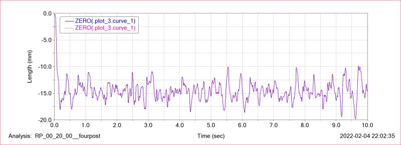
After looking at simulated data it seems that actual motion ratio of spring and damper are identical. Below is damper vs spring displacement (both curves starting points aligned to zero before plotting)

Damper_vs_Spring_Displacement_d9bmkk.png


So I don't know what those lines mean in SVC data but when simulated model seem to behave as expected.

Thank you,
Ted
 
There is a suggestion that all the dodgy numbers in svc reports should be removed until they have been fixed. I use plotted MRs for my reports.

SVC is rather a weird setup, I don't know how it works but it is NOT a k&C test

Cheers

Greg Locock


New here? Try reading these, they might help FAQ731-376
 
Thank you Greg,
There're few more things I wanted to ask:
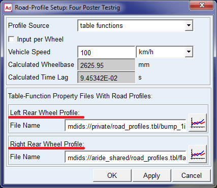
1.It seems that there's some problem with 4post test rig when trying to use table functions as road profiles. I actually starts with dialog box itself. When I choose table functions as profile source, instead of Left Wheeltrack profile (as per Acar help - "6. For the Left-Wheeltrack Profile, right-click the File Name text box, and then search the <aride_shared> database for the file bump_1inch.rpt." ) it is Left Rear Wheel profile (same for the right side):
DialogBox_ljvoaz.png

May be it is some sort of typo...

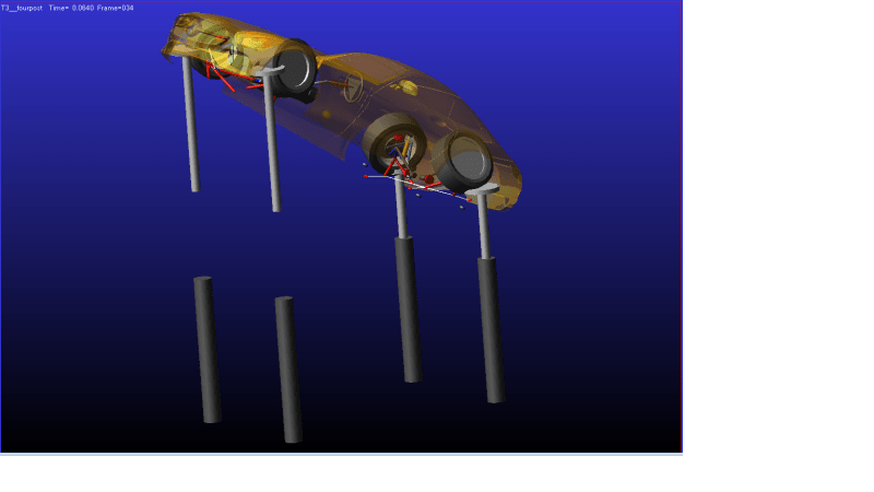
Anyway, when I use example files flat.rpt (right side) and bump_1ich.rpt (left side) and run the analysis the rig would launch the car in the stratosphere.

ExplodingRig_m23qsn.png


If I use flat.rpt under both sides - same weird thing happens. I'm curious if that's me doing something wrong or that's the case of software bug? Using RPC file based road profiles works without problems.

2. In A/car under Tools/Requests there's Request Map Editor dialog box. It is stated in the help file that "Any requests defined in a Request Map will be written to RPCIII format after simulation." However, after the simulation I can't find any .rpc files written.

3. Some time when doing full vehicle simulation A/car gives an error:


---- START: ERROR ----

Static equilibrium analysis has not been successful.
The maximum number of iterations 25, has been reached.
For the last attempted iteration:
The equation with the largest error was model.GT4_Rear_v2.ges_subframe Comp = 6 Error = 0.000000
The variable receiving the largest increment was model.GT4_Rear_v2.ger_lower_strut Comp = 10 Delta = 0.001896.
---- END: ERROR ----

Static Solution failed to converge


Can I increase number of iterations (if that would help) and if so - how? BTW, it doesn't seem to spoil the actual simulation results.

Knowing that you don't use A/car much - may be you never encountered this issues but may be you did and know the solution?

Thank you,
Ted
 
1 - I don't know I haven't used 4poster in Car. An interesting thought is that a test we currently do for which I have a large slab of custom adm won't work in Car. yes it was probably a typo.
2 - .rpc sometimes gets called .rsp - however that command has never worked in Chassis
3 Yes that's very familiar. Increasing equilibrium maxit can help, otherwise you also need to look at error and the other settings in the solver. You'll probably find a model will hit equilibrium in some weight conditions but not others which may give you a clue. Sadly the components identified in the error message are often just the last link in the chain of whatever the problem is, rather than being the root cause. In my own case I have resolved this by replacing an overelaborate beam sta bar with a simple sta bar.

Cheers

Greg Locock


New here? Try reading these, they might help FAQ731-376
 
Thank you Greg!
Currently I'm trying to add Adams Insight to my tool chest for this shaker rig study.

May I ask you:

For Design Objectives I would like to use for example:
Chassis displacement Pitch
Chassis displacement Heave
Tire force normal (CPL)

From available Design Objective value options, I think that Standard deviation is most suitable and it seem to work fine for heave displacement. To verify I exported curves data to excel, and calculated standard deviation. Comparing results to visual examination of plots shows that StdVar correlates well with what plots are showing, i.e. StdVar value is smaller for the plot that shows less heave displacement.
Problem is that with Pitch and CPL it is not as straight forward.
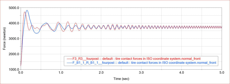
CPL - on the plot is is visibly clear that F_B1_1_R_B1_1 (starting from ~ 0.8sec) force variation is lower then F3_3 plot, yet standard deviation of F_B1_1_R_B1_1 = 254.4 , for 3_3 = 231.95. There's similar problem with Pitch angle.
CPL_gjjrl2.jpg


Is there a proper way to use Adams insight for Design Objectives such as CPL?

Thank you,
Ted
 
Hmmm... I'm not sure I fully understand you. What is Vpp/2.8?

Still the main question is how do I go about using CPL as Design Objective for Adams insight...Is it feasible to use standard deviation during simulation value?

Thank you,
Ted


Vpp = peak to peak amplitude, which look to be around 160 in your plot. Yes, there is no reason in principle why you can't use standard deviation as a response, but as I said, I don't think it is measuring what you think it is. Perhaps it is taking SD of the whole sample, which would be very messy in the case of something with a large DC offset, even if detrended. If I don't like the way Insight is calculating something I export the workspace, substitute the values I want, and then reimport the workspace.

Cheers

Greg Locock


New here? Try reading these, they might help FAQ731-376
 
Thank you!

Yes,those numbers that I posted were calculated in excel using all sample. I think that the moment when ADAMS "drops" the car on the rig creates that "problem". I assume that there's no way to set up request so that it outputs data starting from some prescribed moment in time?

Thank you,
Ted
 
Don't use those yet but I guess that there's no way around learning to use Matlab - it seem to be an essential tool. So I would guess that till I get familiar with Matlab there's no way to answer my question.

Anyway I can do it (process a desired portion of data) in other software - even simple excel.

Let me ask in a more general way... Say I have to arrays of Tire normal load data. My objective is to find a way to get some sort of sufficient way to get some sort of statistical value that would allow me to judge if one data set is "better"
or "worse" and that's what I struggle with atm.

One other question - Adams insight can "drive" Acar simulations according to runs defined in workspace. Is it possible to drive/call Acar/Achassis simulations from Matlab?

Thank you,
Ted

 
Yes for the time being calculating in Excel and filling the workspace in by hand is a reasonable solution, BTDT.

I have never defined a custom response in Insight, I know it is possible. RMS of a detrended sinusoid seems like a good way of describing it, or you could use kurtosis which is 4th power moment and so is more sensitive to peaks. Either are very sensitive to DC offsets, and long term drifts, and detrending is a great way of screwing things up. Ideally I'd high pass filter the signal before taking the rms, or do it all in the frequency domain.

Chassis, yes, by direct editing of the adm in matlab and then run it from the command line. I have run a correlation exercise that was running 4 threads of chassis simultaneously, using the results to drive changes in the adm. Car, we haven't found a way of getting it to build from the command line, and direct automatic editing of the adm no longer works because the adm structure is not consistent. That is, in Car marker and request numbers in particular are no longer stable between builds. It does not seem impossible to build from the command line, but we haven't found it. I am considering doing a global find and replace on marker and request numbers so that the numbering remains stable, but its not a job I look forward to. You can run a Car model from the command line (and hence from Matlab), but I haven't done that yet.


Cheers

Greg Locock


New here? Try reading these, they might help FAQ731-376
 
Car command line can probably be deduced from this

file:///C:/Program%20Files/MSC.Software/Adams/2021_4_856550/help/master.htm#page/adams_car/compo_analyses.html#ww1180377

The .xml can be used to run the simulations in batch mode. No postprocessor will be started after the simulations, but just the simulations will be executed. An example of a macro (.cmd) running the simulations is given below. This macro executed with the command:
Windows:
<release>\common\mdi.bat acar ru-acar b runtest_batch.cmd
Linux:
<release>/mdi -c acar ru-acar b runtest_batch.cmd exit
With the content of the runtest_batch.cmd (running the tiretestrig_batch.xml):
! example cmd for running tire testrig in batch:
! mdi.bat acar ru-acar b runtest_batch.cmd
!----
!
variable create variable_name=filename string_value="tiretestrig_batch.xml"
!
if condition=(!db_exists(".acar.variables.tireTestrig"))
variable set variable_name=ttmp_pyexe &
int=(eval(run_python_code("from mdi.visedit.common.tiretestrig_editor import *")))
variable set variable_name=ttmp_pyexe &
int=(eval(run_python_code("os.environ[\"MDI_PRODUCT_NAME\"]=\"main\" ")))
variable set variable_name=.acar.variables.tireTestrig &
int=(!eval(run_python_code("w_tire_testrig=TireTestrig_editor()")))
end
!
! for loading the acar databases
!
for var=ttmp_index start=1 end=(eval(cdb_get_number_of_cdbs()))
variable set variable_name=ttmp_name string = (eval(cdb_level2db(ttmp_index)))
variable set variable_name=ttmp_path string = (eval(cdb_alias2path(ttmp_name)))
variable set variable_name=ttmp_pycmd &
string=(eval("w_tire_testrig.addDb ('"//ttmp_name//"','"//ttmp_path//"')"))
variable set variable_name=ttmp_pyexe &
int=(eval(run_python_code(ttmp_pycmd)))
end
!
if condition=(filename != "")
variable set variable_name=ttmp_pyexe &
int=(eval(run_python_code("w_tire_testrig.loadFile ('" // filename // "')")))
variable set variable_name=ttmp_pyexe &
int=(eval(run_python_code("w_tire_testrig.runit_clicked(True)")))
end
!
variable delete variable=(eval(db_filter_name(db_children(.__ACAR,"variable"),"ttmp_*")))


Cheers

Greg Locock


New here? Try reading these, they might help FAQ731-376
 
Status
Not open for further replies.

Part and Inventory Search

Sponsor