Generally, I'm looking for information on anchorage zone reinforcement design, but I have a few questions to hopefully clear up some concepts. Skip to the end for my TLDR questions.
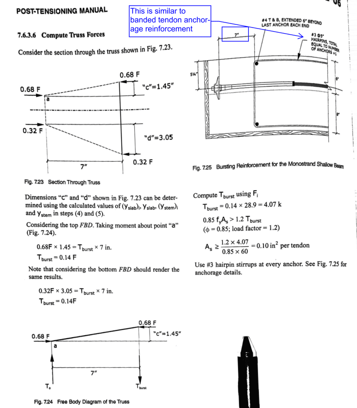
I'm mostly interested in the analysis / design of anchorages for a typical PT T-beam. Reviewing PTI's Pot-tensioning manual (6th edition), they have standard details for anchorage for banded tendons (see below). Note that they use #3 hairpins for each tendon with a couple horizontal bars. The hairpins are located 3/8*t from the anchor. The hairpins serve as a tie for the strut and tie model which makes sense to me. One thing that strikes me odd is that in the "plan view detail" they show the hairpins tight to the anchor device without the 3/8*t gap. Is this just bad drafting?

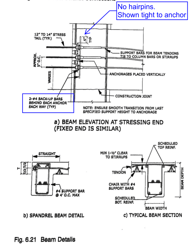
The next question I have when looking at the standard details in the PTI manual is the "standard beam detail" (see below). In this detail there are no hairpins, only straight bars, and they appear to be tight to the anchorage device. These are labeled as "back-up bars" which PTI defines as "Reinforcing bars placed in concrete in the anchorage zone to position in the anchor and help in distributing the loads". They don't mention anchorage reinforcement in the detail. Is this purposely left out or are the back-up bars intended to act as anchorage reinforcement? Maybe they are only there as local anchorage reinforcement (not general zone).
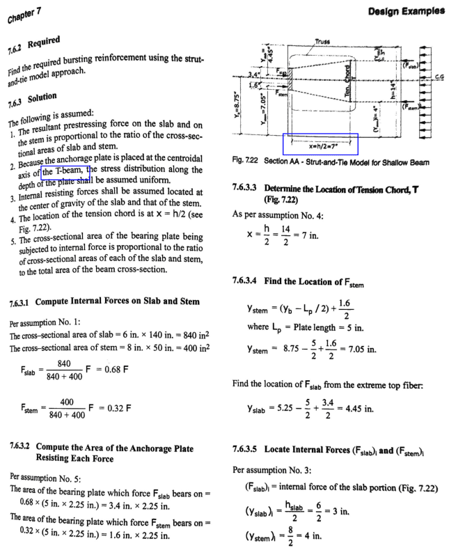
There is an example in the manual for Anchorage Zone reinforcement for a PT beam in which they use the strut and tie model. The reinforcement is essentially the same as what is used in the standard detail for banded tendons (see image below). This leads me to believe that the reinforcement in the standard beam detail is not intended to act as anchorage zone reinforcement. It would be nice if the example didn't assume that the CGS wasn't at the centroid of the section.
I've also looked at PTI's anchorage zone design manual. They do have one strut and tie layout where the tie is located at the anchorage device as shown below. However, I don't believe the standard detail is using this STM, right?

The PTI anchorage zone design manual has an example that is very similar to the PTI manual's example. However, the reinforcement arrangement is different in that they use U-bars as opposed to hairpins (see image below). Is one more common than the other?

TLDR Questions:
[ol 1]
[li] What does your "typical" anchorage zone reinforcement look like for a single span PT T-beam?[/li]
[li] The PTI anchorage zone design manual gives several different strut and tie models to consider and also mention considering the reaction/bearing force at the bottom of the beam. If you have a T-Beam with the anchors not at the centroid, what does your Strut and tie model look like and do you consider the bearing reaction?[/li]
[/ol]
I'm mostly interested in the analysis / design of anchorages for a typical PT T-beam. Reviewing PTI's Pot-tensioning manual (6th edition), they have standard details for anchorage for banded tendons (see below). Note that they use #3 hairpins for each tendon with a couple horizontal bars. The hairpins are located 3/8*t from the anchor. The hairpins serve as a tie for the strut and tie model which makes sense to me. One thing that strikes me odd is that in the "plan view detail" they show the hairpins tight to the anchor device without the 3/8*t gap. Is this just bad drafting?
The next question I have when looking at the standard details in the PTI manual is the "standard beam detail" (see below). In this detail there are no hairpins, only straight bars, and they appear to be tight to the anchorage device. These are labeled as "back-up bars" which PTI defines as "Reinforcing bars placed in concrete in the anchorage zone to position in the anchor and help in distributing the loads". They don't mention anchorage reinforcement in the detail. Is this purposely left out or are the back-up bars intended to act as anchorage reinforcement? Maybe they are only there as local anchorage reinforcement (not general zone).
There is an example in the manual for Anchorage Zone reinforcement for a PT beam in which they use the strut and tie model. The reinforcement is essentially the same as what is used in the standard detail for banded tendons (see image below). This leads me to believe that the reinforcement in the standard beam detail is not intended to act as anchorage zone reinforcement. It would be nice if the example didn't assume that the CGS wasn't at the centroid of the section.
I've also looked at PTI's anchorage zone design manual. They do have one strut and tie layout where the tie is located at the anchorage device as shown below. However, I don't believe the standard detail is using this STM, right?
The PTI anchorage zone design manual has an example that is very similar to the PTI manual's example. However, the reinforcement arrangement is different in that they use U-bars as opposed to hairpins (see image below). Is one more common than the other?
TLDR Questions:
[ol 1]
[li] What does your "typical" anchorage zone reinforcement look like for a single span PT T-beam?[/li]
[li] The PTI anchorage zone design manual gives several different strut and tie models to consider and also mention considering the reaction/bearing force at the bottom of the beam. If you have a T-Beam with the anchors not at the centroid, what does your Strut and tie model look like and do you consider the bearing reaction?[/li]
[/ol]