Eng-Tips is the largest engineering community on the Internet

Intelligent Work Forums for Engineering Professionals

Post Tensioned Beam - Anchorage

Status
Not open for further replies.

strguy11

Structural
Nov 29, 2005
229
0
0
US
I have a parking garage beam/slab system i am designed. Beam span is about 56'. 7" thick slab, beam dimensions are 24" wide x 32" deep. My preliminary design shows i need 27, .5" diam tendons.

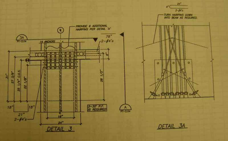
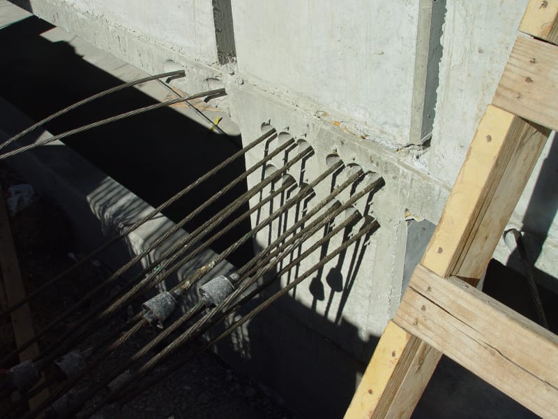
Question is about about the end anchorage. I have read that it is preferred to have the anchorage at the CGS of the beam. Doing this is about 13.3" from the top of the beam. Problem I am running into is based on the anchor size (5"x2.25"), i cant fit the anchors within the reinforcing stirrups of the beam and have the centroid of the anchor group at the CGS of the beam.

I have seen some example plans that would seem to have this issue, however they dont show a size of the tendon, just an effective force. Does the PT supplier just "work this issue out" and figure out how to make it work? I guess going to a 0.6" tendon could be an option, with less anchors, but again, is this the option of the PT supplier? I was using a monostrand unbonded system.
 
Replies continue below

Recommended for you

That is a bunch of PT: 700+ kips for a 56' span. What are your beam spacings for your 7" slab thickness?

It is sometimes possible to sweep a few tendons into the slab (top flange of beam) to maintain your CG. Can be tough to miss column rebar and also maintain cover.

Capturept_beam_car8ac.png


captureptbeam2_vkkauq.jpg
 
What slab width are you using to determine the centroid?

For what I understand US designers often use the full panel width. The argument used is that the P/A spreads over the whole width. That is true under transfer conditions but not at ultimate strength condition which is the important one so it is completely illogical but forgetting that,

if you think about it, the prestress force is being applied to the beam section . As you move away from the anchorages, the force will then gradually disperse into the slab at about 30 degrees to the line of the beam.

So at the anchorages, the centroid is at the centre of the beam web alone. As you move away from the anchorages, the centroid rises gradually to the final assumed centroid as the P/A disperses into the slab.

Most designers ignore this and use the centroid of the T section for simplicity as varying width centroid introduces other forces into the calculations due to the changing slope of the centroid line that certain popular PT software in USA cannot account for.

But to assume anchorages at the centroid of the T section using the full panel width is completely illogical.
 
rapt said:
What slab width are you using to determine the centroid?

Based upon strguy11 13.3" CG from top, the effective flange used calcs out at: 24" beam web + 30" = 54" total.

The latest PTI Guide for Design of PT Buildings (2011) states:

PTI said:
"The prescriptive requirements for effective flange width required by ACI 318 for nonprestressed monolithic T-beams are waived for prestressed concrete T-beams. Engineers of prestressed concrete T-beams can use any dimension for effective flange width, ranging from the beam web width only to the full panel tributary of the beam...

Engineers are encouraged, however, to use the prescriptive requirements for nonprestressed beam flange widths (for example, 16 times the slab thickness plus the beam web width for an interior beam)."


I am using the effective flange with of 8*slab thickness on each side of the web, which would be 136". For the CGS, it is 9.68" from the top of the section. (The 13.3 from above was from memory). I can still get the beam to work if i move the anchorage down to the CGS of the beam itself (i.e. 17"), but i have always been told to locate it at the CGS of the T section.

Like i said, I have an example set of plans that is pretty close to my actual project, with the similar beam sizes and PT effective forces, but they show the anchors at the CGS of the T section, and i dont see how they got the anchorages to work.
 
The example set of plans i have is using 725 kips effective force, for a 24"x34" beam with a 7" slab. Beam span is 62' and spacing is 29'. at ends of the beam, the PT profile is listed at 23.625" above the bottom of the beam, which is 10.375" from the top. I calc the CGS of the beam to be 10.385" from the top, when using a 136" eff. flange width.

Based on this, i am just wondering how this all worked because i can see how the anchors would have been oriented.
 
Good to see someone ignoring the rubbish rule from ACI which interestingly was initially put in on PTI advice.PTI have now changed their tune..

Even then, technically, the shape at the anchorages is the rectangle as none of the P has dispersed into the slab yet.
 
I guess, one option would be to use 0.6" tendons, for less strands. Anchors are bigger, but it might work out as well. Perhaps that is what the example did, as those plans do not list a PT tendon size. Is this typical in the US to leave that part up to the supplier? I have always specified 0.5" tendons, but since we are only looking for an effective force, it could be an option to use larger strands.


Thoughts?
 
Status
Not open for further replies.
Back
Top