FEA way
Mechanical
- Nov 13, 2018
- 5,138
Hi,
I would like to ask how the Load Proportionality Factor (LPF) vs displacement plots obtained from post-buckling analyses using Riks method should be interpreted. From what I've read actual load = applied load * LPF. So when I apply a critical buckling load obtained from eigenvalue (linear) buckling simulation to the imperfect geometry and get LPF vs displacement plot with LPF below 1 (about 0.8 - 0.9) all the time then does it mean that critical buckling load wasn't achieved (due to convergence issues) and thus the plot doesn't represent actual postbuckling behavior ? Or does it mean that the actual critical load value is smaller than what I've expected after linear buckling simulation and postbuckling was simulated ?
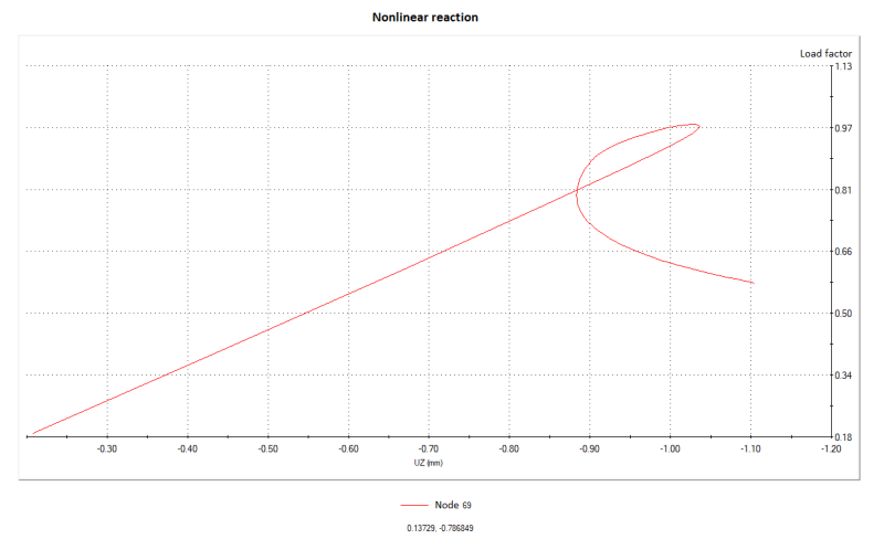
Here's an exemplary plot from such analysis (cylindrical shell under compression with trigger load of 1% of critical load applied in the direction of first buckling mode shape):

What does the loop at the end of it actually mean ?
Thanks in advance for your help
I would like to ask how the Load Proportionality Factor (LPF) vs displacement plots obtained from post-buckling analyses using Riks method should be interpreted. From what I've read actual load = applied load * LPF. So when I apply a critical buckling load obtained from eigenvalue (linear) buckling simulation to the imperfect geometry and get LPF vs displacement plot with LPF below 1 (about 0.8 - 0.9) all the time then does it mean that critical buckling load wasn't achieved (due to convergence issues) and thus the plot doesn't represent actual postbuckling behavior ? Or does it mean that the actual critical load value is smaller than what I've expected after linear buckling simulation and postbuckling was simulated ?
Here's an exemplary plot from such analysis (cylindrical shell under compression with trigger load of 1% of critical load applied in the direction of first buckling mode shape):

What does the loop at the end of it actually mean ?
Thanks in advance for your help


